Wednesday, January 5, 2022

Honeycomb Ultralight Cabin

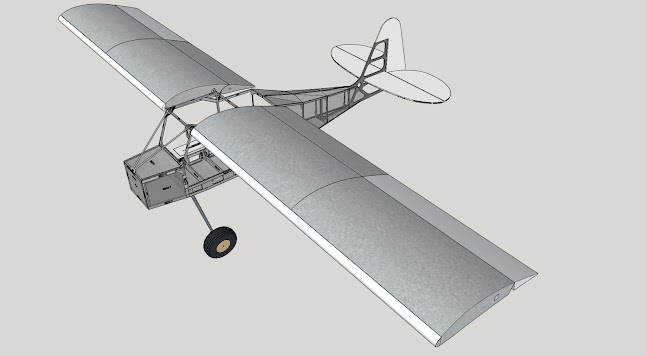
The last two days have been spent starting to put together my ultralight kit aircraft. I'm pleased with my progress; I currently have 19 hours in the build. When finished, my Chipper UltraCub will look a lot like this:

Yeah, you have to use some imagination to make that real plane. An engine would help. Also, a propeller, a windshield, a coat of paint, and some control systems.

My efforts this week are focused on the cabin and rear fuselage. Drum roll, please... here's some photos at the end of today, Wednesday.

What you are looking at is a cabin which is very similar to earlier ProCubs and UltraCubs from Belite Aircraft. Structurally, it is built from honeycomb aluminum and a lot of sheet metal.  The honeycomb is used very smartly, using pre-cut strips, so very little is wasted.

I am providing the plans for this ultralight to my Patreon subscribers for $10 / month. Terms & Conditions apply.  Here's the link: www.patreon.com/jameswiebe  You can also indicate your desire to purchase a kit for $35 / month. I need the support, and I appreciate it very much.

Looking inside the cabin from the rear, here's the view:


And here's another view.


The main idea in this design is to surround the pilot with a cage, constructured of honeycomb and extruded aluminum, so that the occupant is well protected in the event of an accident. The size features are similar to my past commercial designs, a tall person will fit well, and a big person will fit as well. 

The exterior width is 25", and I am 6' 2"+. 

For example, the firewall frame is constructed from 3/4" thick honeycomb. These pieces are brute strong, yet very light. This is 12 ounces of honeycomb:


I used my shopbot to cut various gussets, providing exact fit and awesome quality. Here's some samples.


The most impressive gusset so far in this project is the side gusset. It ties together the forward cabin, a lot of honeycomb, and the rear fuselage while weight very little and providing predrilled holes for easy assembly. It's nice.


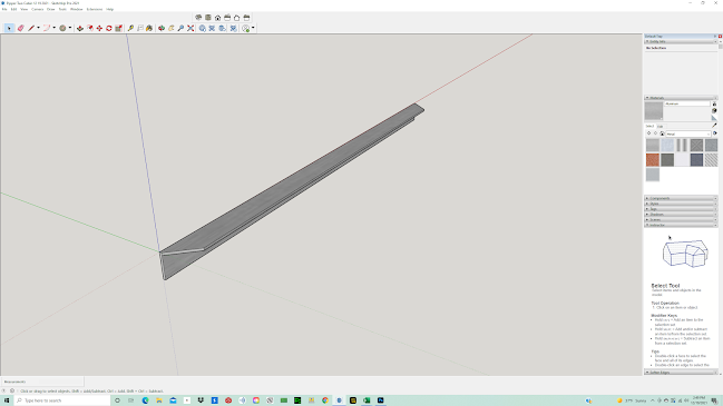
I'm also using stock aluminum structural angle, which requires hand drilling. Here, I've marked a part with a drill pattern.

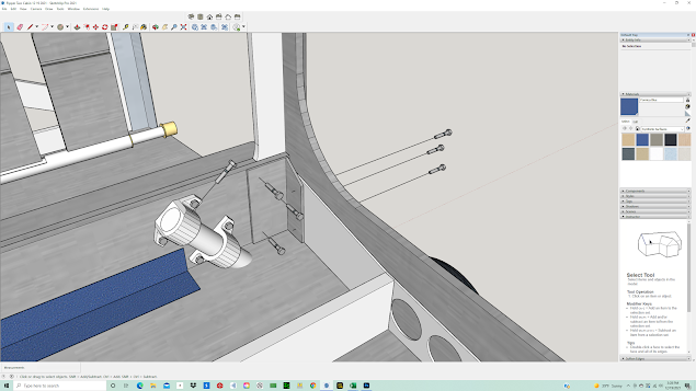
You can see that part attached to a bulkhead, in the below photo. Also note how my predrilled angles have been used to attach the bulkhead to side honeycomb.


As I indicated before, I am providing the plans for this ultralight design to my Patreon subscribers for $10 / month. Terms & Conditions apply.  Here's the link: www.patreon.com/jameswiebe  You can also indicate your desire to purchase a kit for $35 / month. I need your patreon support, and I appreciate it very much!!!

The most requested feature is folding wings. Naturally, this design has wings that fold.


Monday, December 27, 2021

Service Bulletin #5 Correct Wheel Alignment

 Service Bulletin #5 Correct Wheel Alignment

This SB #5 is advisory in nature.

When assembling landing gear, particularly wheel assembly, take care to ensure that alignment of the wheels is correct. The lineup of the wheel should be straight to ground travel path; toe-in and toe-out must be avoided. Toe-in will cause landing gear chatter.

Alignment is ensured by correct rotation of the landing gear shaft before pinning in place at the upper bulkhead fitting.

The following picture shows correct alignment. The green line denotes the vector of the ground roll relative to the tire.


The following picture shows incorrect alignment, which causes minor to severe gear chatter on takeoff and landing. The orange line is as incorrectly assembled; the green line is what it must be reset to.


Tuesday, December 21, 2021

James launches a Podcast!

In this age of social media, I'm loving the way that I can connect my passion for aircraft with you!

I've been doing this in multiple ways: this blog, Facebook, email communication, patreon, Youtube, instagram, and now... drum roll please... an occasional podcast.

Well, it's really more like a video podcast. 

In yesterday's very first episode, I explain some of the design decisions behind the Chipper ProCub / UltraCub, along with a tour of some of the FAR Part 103 features that the design has.

You can see and hear it on YouTube, here:

https://youtu.be/iBtjWFirmBA

You also get to see my messy office.

I'm looking for ideas of topics you'd like me to cover. I'm looking for feedback on how to as interesting as I can for you!


Sunday, December 19, 2021

Mandatory Service Bulletin #4 - Installation of stronger gear head bulkhead

Mandatory Service Bulletin #4

Supercedes MSB #1


The purpose of this MSB is improve the strength of the main gear head bulkhead, replacing the original 5.25" x 0.25" machined part with a solid, larger part.

The desired outcome is a bulkhead which will enlarge the footprint spread of the landing gear brackets, which reduces torque caused by landing stresses, and also allows for a greater distance for bolt holes to the edge of the bulkhead, reducing or eliminating the problem of cracking.

Also included is a much larger angle piece for each side, allowing for better transfer of landing gear loads into the side 1/8" aluminum pieces.

This MSB also contains directives for potting bolt locations within honeycomb, substantially improving strength. 

This MSB also contains directives for bonding metal surfaces such as angle and flat sheet, which will substantially improve the strength of connected components and provide improved longevity for the airframe over time and service cycles.

This MSB allows future use of the bulkhead for hard points such as floats, shock absorbers, ski's, under fuselage storage container.

This MSB is required prior to installation of shock absorbers, which will be required for a possible future Gross Weight Increase to 1320 pounds.

Estimated time to install: 60 hours

Review and understand ALL INSTRUCTIONS prior to performing any work. As an example of one possible sequence error, potting of honeycomb for bolt installation is mandatory and must be performed prior to assembly. Without reviewing this material first, you may find it difficult to pot your honeycomb in sequence.

Supplied Materials:

1) this MSB manual, complete with large printed illustrations

2) 41" x 6" x 0.25" 6061T6 aluminum bar, solid

3) 41" x 2" x 2" x 0.188" 6061T6 aluminum angle, cut with dogleg angles at each end

4) 6" x 3" x 2" x 0.188" 6061T6 aluminum angle, cut to shape and pre-drilled (advise if you do not want it drilled)

5) 2" x 2" x 24" x 0.040" 6061T6 aluminum angle, bent to shape and predrilled with rivet location holes

6) AN nuts, washers, bolt kit

7) 1" aluminum square tube, separately used to actuate flaps (not a part of this MSB, but missing from many kits).

Needed but not included:

1) scrap material: honeycomb aluminum

2) bonding adhesive, such as 3M 2216

3) rivets

4) 80 grit sandpaper

5) acetone

The original design is similar to the following CAD illustration, where the main gear bulkhead has lightening holes. Other details within this CAD illustration are not consistent with shipped kits.


Remove existing structure and test fit solid cross bar. 

Roughen surface of aluminum and of facing honeycomb with 80 grit. Clean with acetone or similar. Bond with adhesive and consistent pressure.


Cut a scrap of aluminum honeycomb to fit in the reverse top gap, sand, clean and bond as well.


Reverse side showing scrap honeycomb bonded in place.


The 2" x 2" x 3/16" angle piece looks like this:


And it is also prepped for bonding on the facing surface.  Bond it in place:


The 3" x 2" x 6" angles come pre-cut, as shown. Also pre-drilled. Please advise if you do not want them pre-drilled (for instance, to match existing hole locations at assembly).


Surface prep them by sanding and cleaning, then bond in position with adhesive and clamps. Do not crush honeycomb when clamping.

The bottom angle is constructed of .040 6061-T4 aluminum and is pre-bent and predrilled. Surface prep, bond in place, then rivet in place.


Bolt locations going through honeycomb must be potted with epoxy prior to bolting. The six bolts going through the corner angle are AN4.


(Anecdote: also shown is the recommended location for the AN3 shear twist bolt, going into the top landing gear bracket.)

The exact location of the landing gear brackets is provided in the final document accompanying your upgrade kit.


Two AN4 bolts are installed into the top, spaced 13" apart and 0.75" below the top line.

The center stick support is installed. Note the bend in the support and shimming as necessary for exact, friction-free, and backlash free use of the stick.


Drill and route fuel lines, rudder cables, etc., as required for your unique installation.