Wednesday, November 24, 2021

Improving strength in a landing gear bulkhead


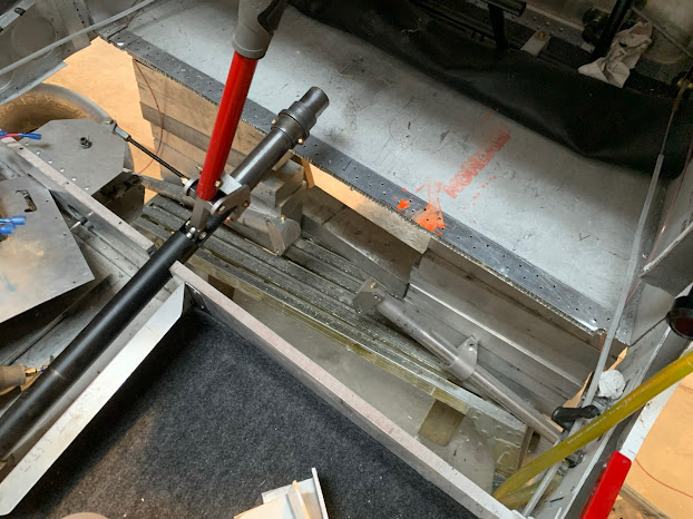
I'm working on upgrading my landing gear bulkhead. Jumping right in, this is how things look after I've removed the broken parts.The leftover angles are still visible, but I removed them later. It was easy to remove the fuel lines on the right hand side, but the rudder cable was a stickier wicket. I ended up cutting it at the thimble, and will reuse the same line and install longer stainless straps to resolve the shortened cable.  Also in this photo, I've not yet removed the bottom aluminum. After everything else is done, I will re-sheet that section.

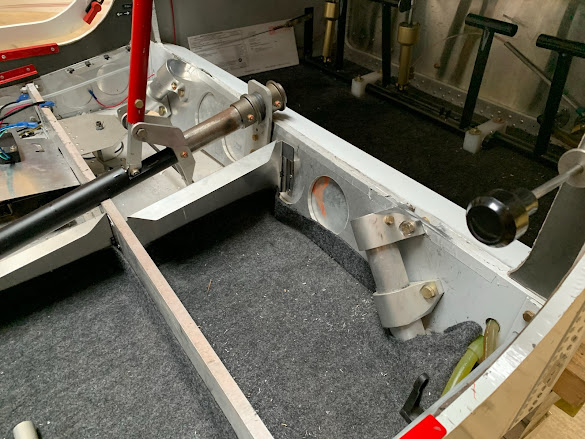
This is the left side of the work area. The 1/8" material remained bent. It had reached yield load but not ultimate. After consultation with CW, I concluded to leave it. The new angle was clamped and bonded into place, and the new top and bottom bolt holes are substantially to the left o the existing holes. The new middle bolt hole is centered between the old holes.


Right hand side with old angle finally removed.


Now, I drill out rivest and cut out the bottom skin. I should have done this earlier, it makes everything easier.


Seizing opportunity, I removed rust from the 1 3/8" steel tube. It will get blued or painted. I also discovered that the AN3 bolt holding on the bushing was over-tightened, which made the oilite bearing not work smoothly, thus diagnosing a minor background squawk.


Cocoa cuddle break.


Unused rivet holes are filled with epoxy. This restores the integrity of the HC. Do the same with unused bolt holes.


It would be better NOT to drill out the outer skin, but I did. Use something (for instance, a very small allen wrench) on an electric drill to clear out ALL of the honeycomb for an area equal to or greater than a fender washer. Pot all holes with high tensile epoxy compatible with aluminum. JB Weld original formula; 3M 2216 are good choices. I did it when the hangar was very cold so it made it easy to do with masking tape and no dripping.  YMMV.  My glue wasn't runny.  It was glop.

This is new required procedure for all bolts going thru HC. 


Same thing from the inside. You can see the epoxy which has oozed through the drill holes.


The top angle is bonded into position, as the are the left and right side attach angles. All surfaces between bulkheads and angles need to be heavily roughed (grinder or 60 grit), cleaned, attached using appropriate metal bonding epoxy.


Here's the left angle, which was machined to fit, partially bolted in place.  The red wire is power going to the flap and droop linear servos. Not all bolts are done.  The lower angle (which is impossible to see) is not yet in place.


The right angle bonded and partially bolted in place.


To be continued....


Tuesday, November 23, 2021

How to make a plug for Composite Amphibious Floats

Ever wanted to fly on water?

First of all, this is a work-in-process.  The plug is not yet complete. In fact, as I write this, it is in storage, ready for next steps. That next step would be to finish the plug, and then use it to either make a mold or start making parts.

Secondly, this is just a pictorial journey.  

As a brief overview, I created a design for a float in CAD, then exported into slice files for cutting in foam. They were stacked and shaped, then glued to a plywood bottom base. Fiberglass was applied for strengthening, also some aluminum rails.

And that is where the project sits now. It's in storage.  :-/


Monday, November 22, 2021

Breaking the Landing Gear Bulkhead on my Chipper 2

Stupid Pilot Tricks...

I had just installed the new oil thermostat in my Chipper 2.  I pulled the plane out of the hangar, eager for a break in the routine.  (I was early in the process of installing shock absorbers on the plane.) It was a beautiful afternoon, the sky was blue, the grass was green, and the plane was gorgeous.  

Chipper 2 N318KW stock photo, before recent events.

As usual, my UL350iS powered up without a hitch. My goal was simply to warm up the engine and check oil pressure & temps. The process of warming up was taking a long time (it was a little chilly) and I advanced power while keeping the brakes engaged.  This went on for several minutes. I edged the power up a bit more. My brakes were having a hard time keeping the plane from creeping forward. I'd ease back on the power, hold the brakes a little tighter, and advance power again.

All of this was extremely poorly thought out.

After advancing power again, the plane started to list to the left and settle down to the ground, like it was kneeling. Realizing that a prop strike was imminent, I retarded throttle. The tip of the prop cut into the soft grass and dirt, carrying through several blades before all became silent.

I broke my plane.

I did not take a picture. I was flaming mad. My hangar mates swiftly emerged from a hangar backroom, having heard the commotion, and walked towards me as I got out of the kneeling airplane and looked at one gear leg bent backwards. I realized that I had twisted the gear attach bulkhead. (The gear leg was not hurt.)

Then I realized I had forgotten to re-install the trailing links, so I had just ripped my gear out because of my forgetfulness.

With the help of my friends, we rolled the wounded bird back into the hangar. 

The inside of the cockpit looked like this:

And after several days of drilling out rivets, chopping out aluminum bulkhead, and cutting / pulling / fussing / fuming, the removed bits looked like this:

Over the course of the Thanksgiving holiday, I will be stepping you through what I have learned on how to repair this problem in my Chipper. I have also been using this opportunity to solve some other problems.

1) Improved bulkhead assembly for potentially higher gross weight

2) Shock absorber installation for potentially higher gross weight

3) Improvements in mounting techniques for bolts in honeycomb

4) Improvements in bonding techniques

5) General proof that this structure is repairable

And as I head into the Thanksgiving break, things are much improved. Here's a photo of how things were looking earlier this afternoon.


I do all my airplane stuff at 29KS, which is the Wichita Gliderport. It has many very smart aviation people who hangar there and build / rebuild / repair things there.

The benefit of this unfortunate event is that I am receiving honeycomb repair and assembly advice from another of these hangar mates. 

I'm going to take a moment out to brag on some of my aviation friends:

    N.: ex-CTO of Mooney Aircraft
    CW.: A&P/IA, formerly with Textron, traveled the globe fixing King Airs, versed in everything including honeycomb
    D.: A&P/IA, formerly built parts for Mosquito Helicopters, currently starting a Piper Cub parts company, currently rebuilding 3 Cubs, has built 7 Pietenpols lifetime to date, with the last one nearly done right now
    CP: 50 years with Cessna engineering, knows everything about any piston aircraft they designed. He can tell you why various Skylanes had weight changes, cabin changes, structure changes, feature changes. He is the walking and talking encylopedia of Cessna singles. 
    K: Designed composite propellers for McCauley, currently working for Textron special ops.
 
In particular CW has taken an interest in Chipper 2 and its proper repair. 

Bottom line: after this rebuild, I believe that the gear mounting bulkhead will be strong enough so that failure will not occur when the trailing link is not installed.

Thanks for reading. Please "Follow" this blog by clicking on the Follow button.  You'll be advised every time I post the next article.

Live & Learn.


Friday, October 29, 2021

Is Now the Time for Electric Ultralights?

 The biggest use of ultralight aircraft is to enjoy flight. To that end, is now the right time for an electric ultralight aircraft? I've been there and done that and want to share my history with you.

My History with Electric Ultralights

I've designed and flown electric aircraft. I threw a lot of money into this one, which featured a carbon fiber fuselage and wing. It is called "SkyDock". I developed it with a gas engine as well.

Electric Ultralight Aircraft

Electric Ultralight in flight

A couple of years before that, I adapted an electric motor to a classic Belite ultralight.

UltraCub ultralight with electric motor

UltraCub Electric Aircraft in flight

To help answer the question:
  1. Ultralights are flown for fun; and electric flight is super fun!
  2. Electric motors are available with incredible value and excellent power;
  3. The best batteries ever are now available;
  4. U.S. ultralight law allows individuals to do this experimentation easily;
  5. Even a company or two (eg: Chip Erwin and Merlin) are publicly showing their work with electric ultralights.
Electric Installations:

Consider a single vs dual motor installation. The SkyDock was setup with two motors, while I flew the Belite with one motor. One of my customers used a very interesting single motor design for his converted UltraCub.

Electric Motor on UltraCub Ultralight

Electric Motor on Ultralight Aircraft

SkyDock with dual Electric Motors

Want to see the electric motors on Skydock doing their thing?:


And even more details of how the Skydock Electric motor installation was designed:

Electric Motor Installation in Skydock

Electric motor in Skydock

Electric motor development for ultralight

Is Now the Time for Electric Ultralights?

Yes, it is.
  • Electric flight in ultralights is proven by myself and others.
  • Batteries can produce acceptable flight times for ultralight aviation.
  • FAR 103 and Experimental rules allow it.
  • Bonus: Electric motors are less expensive than gas motors. (Although offset by battery acquisition costs.)
  • Electric flight has a unique sound signature, better and different than any gas motor.  It's just the prop and the airframe, no combustion sounds!
For further exploration:

I recommend you join this Facebook group, run by Bill Esker: