Showing posts with label construction. Show all posts

Monday, January 7, 2013

Belite Aluminum Ultralight Aircraft Cabin Construction, #8

Please note: James' blog has moved to a Wordpress site. To access it, please visit http://jameswiebe.wordpress.com/. All posts have been transferred to the new site, and all new posts will only be accessible via Wordpress. Thank you for your interest!


This is series #8 in our Belite Aluminum Ultralight Aircraft Cabin Construction articles.

It's back to work on the aluminum cabin for a Belite ultralight airplane!  We're going to be working on the internal details now.

BTW, your cabin should now be covered.  You'll need to take care as the cabin is worked on, in order to not tear or scratch the dacron fabric.  This is critical because you'll be slitting the fabric and mounting the landing gear center brace through the fabric.

We've taken the liberty of additionally covering our cabin  with turquoise Oracal, which is our fantastic covering method.

Our two tasks today are closely related:  we'll mount the landing gear cross brace, and we'll build and mount the control stick mount box.

There are two landing gear cross brace plates.  They look like this:

Landing Gear Cross Brace Plate for Belite Ultralight Aircraft.

After bending each piece, and slitting the fabric on the bottom of the cabin, the pieces are inserted through the slits and riveted in place.

Landing Gear Cross Brace Plates inserted through slits in fabric
Landing Gear Cross Brace Plate riveted in place
Two short pieces (approximately 4 1/4") of 3/4" thin wall square tubing are cut in place and clamped, as shown in the photo below.


Landing Gear Cross Brace Plate with tubes clamped in place.
Rivets in place on Landing Gear Cross Brace Plate
another view of Landing Gear Cross Brace Plate
 Now collect the three pieces of metal which comprise the control stick support box.  
Control Stick Support Box sides
Control Stick Support Box top.
Side with tabs bent.   Use a brake, or a vise, or wide jaw pliers, or helpful friends.
Top with bend
Box with clecos.
Box with rivets.

Box clecoed to cross box.
 Note that in the following photo, the steel pivot arm has appeared.  You'll want to check fit with it very thoroughly before riveting, as the instructions for its mounting follow!  Also note that the attachment bolt is an AN4-7 with washers and a locknut.

Box riveted to cross box.
 So let's investigate what needs to be done to attach the steel pivot assembly.

Bearing for pivot assembly.

Bearing bolted in place with two AN3 bolts.  Do not overtorque!
Closeup of AN3-17 bolts used to attach bearing.

Test fit.  

 The control stick pivot should rotate with complete freedom.

Another view of assembly, complete.


Saturday, December 22, 2012

Belite Aluminum Ultralight Aircraft Cabin Construction, #3

Please note: James' blog has moved to a Wordpress site. To access it, please visit http://jameswiebe.wordpress.com/. All posts have been transferred to the new site, and all new posts will only be accessible via Wordpress. Thank you for your interest!


This is a third in a series of article on how to build a Belite aluminum cabin.

The first in the series may be found HERE.

The second in the series may be found HERE.

Random reminder:  All of the standard warnings and disclaimers apply.  Flying a Part 103 Ultralight Aircraft may be dangerous or deadly.  These aircraft are not certified under any FAA regulations.  They are not built from certified aircraft materials.  You are required to sign our standard liability release before we'll ship you a plane or a kit.  You take full responsibility for your aircraft and its operation, per federal law, and per our liability release, no matter who built it.  (Us, you, or someone else...)

Sigh...  American liability...   Now, onward.

****

The cabin in the Belite Ultralight Aircraft has several noteworthy, eyebrow raising features.  For instance, I am very pleased with the number of storage / baggage compartments which I've been able to design into the plane.

Before we get started with today's construction, let's look at some photos which preview the results of your construction project!

Belite Ultralight Aircraft Cabin Assembly, with teal blue Oracal

Three individual storage / baggage compartments, with solid aluminum bottom

Chart compartment, on left side of cabin
***

Now, directly on to the construction.  We'll pick up where we left off in the last installment.

Cut thin wall square tubing for the front seat cross box, and then cleco the two skins to that tubing.

Thinwall tubing for Front Seat Cross Box.  Note one short center piece missing.
You'll need to cut and fit the short tubing piece and cleco it in place as well.  I'm sorry it missed the above picture, but it is in the next picture, below.

Skins, clecoed to tubing for front seat cross box assembly.  Short piece is clecoed inbetween.
Now we'll work on the baggage divider for the front compartment.

Baggage Compartment Divider

There are three baggage dividers.  Select the one for the front compartment, which looks like the photo, above.

Front Baggage Divider, after bending tabs.

After bending tabs in a box break, the divider will look like the above photo.  The divider is then clecoed in place, and it will help to support the front seat cross box assembly.

Front Baggage Divider, clecoed in place.
Front Baggage Divider, riveted in place.
Front Seat Cross Box, riveted together
Front Seat Cross Box, riveted together with quartering view
Then we proceed to the Middle Seat Cross Box.
Middle Seat Cross Box, cleco assembly identical to Front Seat
Now we need to make a notch in each longeron, immediately after the Front Seat Cross Box.  Make a mark as shown below:

Mark in longeron.
Cut notch in longeron.
The notch will allow us to bend the longerons up, about 5 degrees.  The actual angle is determined by the precut side skins, which are coming soon.

Side skin being cut.
Side skin clamped onto side of cabin assembly.
The bend in the side skin determines how high to bend up the longeron.  A clamp in the above photo is holding the longeron against the side skin, so the angle is perfect.  Note the clecos already holding the side skin as well.

Closeup of overlapping star gusset.
Note how everything overlaps.  The top door side skin (not yet installed) will overlap into the same area and determine the final angle of the vertical longeron, and that is why its holes have not yet been drilled through.

Even more clecoes in the side skin, while Lucky snoozes.
One of our shop cats got in the photo.  Our cats are named Second Chance and Lucky.  Both are gorgeous and friendly.

Bottom Cross Lift Strut Tension Member and rear structural angle parts
Cut the three parts as shown, above.  The bottom Cross Lift Tension Member is 1x1x.063 6061T6.  It is NOT thinwall tubing.  At 6Gs of (hypothetical) lift, this piece is carrying around 5,000 pounds of tension.  (And on paper, it's good for it.)

Error in side skins
When this production prototype was under construction, the side skins did not have a rear 1 x 1 notch.  Yours should have a notch, but the longeron will still need to be cut out, so that they look like this:

After notchout and longeron cut.
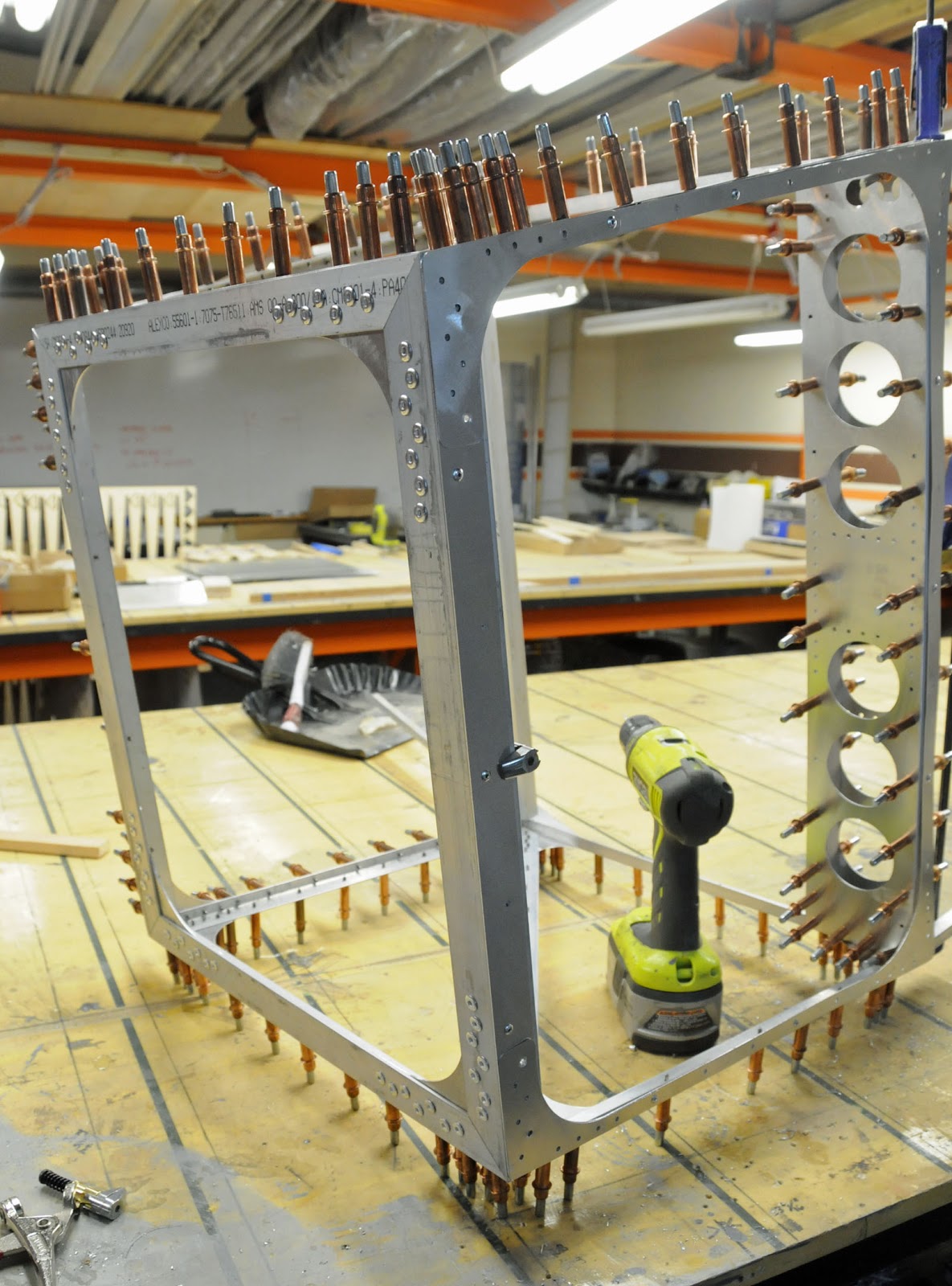
The cross member will form the base of the rear cabin.  Construct the rear cabin cross box:

Rear cabin construction begins.
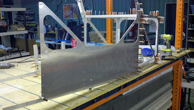
Rear Cabin Cross Box with rear skin.
Add the thinwall tubing.

Thinwall tubing for top of Rear Cabin Cross Box.

Thinwall tubing placed into Rear Cabin Cross Box.
Now, it's time for some riveting.  Note rivet sizes as always, based on the photos:

Rivets on Cross Boxes.

More rivets hold side skins and cross boxes.  WARNING:  Extra rivets shown!
The warning refers to a few extra rivets which have been placed, and which will have to be drilled out to attach Rear Fuselage Gussets.

The Cross Boxes must be aligned perfectly with the pre-drilled holes on the side skins.  I failed to do this on one of the Cross Boxes in this production prototype, and you can see that the middle Cross Box is leaning towards the camera, perhaps by one degree, in the photo below:

Mis-aligned Cross Box, (very slight).  Don't make this mistake!
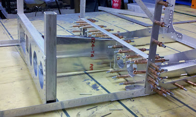
Lucky strikes another pose, with rear of cabin assembly
Another view of rear, this time with rivets drilled out and replaced with clecos.
This is a good time to stop for the day.  The Belite ultralight airplane cabin is beginning to look like a cabin!


Saturday, December 15, 2012

Belite Aluminum Ultralight Aircraft Cabin Construction, #2

Please note: James' blog has moved to a Wordpress site. To access it, please visit http://jameswiebe.wordpress.com/. All posts have been transferred to the new site, and all new posts will only be accessible via Wordpress. Thank you for your interest!


This is the second section on building an aluminum cabin for a Belite ultralight aircraft.  We're well on our way to finishing an awesome cabin for a single place airplane.  When completed, this cabin will weigh about 22 1/2 pounds and will match the look of other experimental (and factory) airplanes costing much, much more.

The first section in this series is HERE.

All caveats and warnings from that section apply in this section as well.  Remember, under federal law, you are personally responsible for ensuring the safety of your ultralight aircraft every time you fly, so do a good job.

Start by cutting two lengths of structural aluminum.  Each piece looks like this:

Short length of angle aluminum.
And each piece fits on the left or right side of the front cabin cross box assembly, as seen in this photo:

Short length drilled and clecoed in place.
Note that a long clamp is being used to pull both sides of the cabin snugly together.

Front Cabin Cross Box with both skins clecoed in.
Now it's time to clamp in the bottom gusset.

Bottom gusset clamped in place.
Bottom Gusset gets a few rivets.  (Cabin is on side.)
Be judicious in the use of rivets on the bottom gusset.  In the above photo, there are a couple of rivets placed (mistakenly) which were immediately drilled out in order to allow the floor pans to slip into place.  However, the objective is to get all of the bottom rivets in, so that the cabin assembly can set on the bottom and moved around without dragging the bottom tips of all of the clecos.

Floor pans as received and after bends.
Your pair of floor pans need to be bent into shape, as shown above.  The pre-cut relief slots make this easy to line up and do. Also, if you have shorter legs, you may wish to drill out and reset the position of the rudder pedal and brake bearing holes.  In general, the position of the holes should work well as set for pilots between 5' 8" and 6' 4" in height.  Shorter pilots may use a back cushion on their back seat, and anyone with truly short legs should consider resetting the pedal location.

Floor pans clecoed in place.
Make sure your floor pans are put in square to the cabin assembly, as one end does not have matching drill holes.  Also note that doubler gussets have been clecoed in on each forward corner.

Bottom front section riveting.
Above is a photo that shows what it looks like after riveting the bottom front section.  Note that many holes have been drilled out for 3/16" rivets.  Also note:  look through the remainder of the assembly instructions, as a metal sheet will be slipped under one side of the floor pan.  The metal sheet is the bottom of the mid cabin storage cabins, and its front edge has to slip under one of the floor pans and also under one of the front landing gear gussets.

Front Landing Gear Gusset.
To be continued.