Showing posts with label aircraft construction. Show all posts

Tuesday, January 1, 2013

Belite Aluminum Ultralight Aircraft Cabin Construction, #6

Please note: James' blog has moved to a Wordpress site. To access it, please visit http://jameswiebe.wordpress.com/. All posts have been transferred to the new site, and all new posts will only be accessible via Wordpress. Thank you for your interest!


#6 in the series.

We will start by attaching the rear fuselage attachment gussets.  There are six:  two on each side, and two on the bottom.  The top side gussets, the bottom side gussets, and the bottom gussets are each unique.  They may vary slightly from these photos in appearance, due to fit and lightening improvements.  Fit, cleco, and rivet them in place, as shown in the following photos:

Bottom Side Gusset and Bottom Gusset, clecoed in place
Bottom Side Gusset, riveted in place
Top and Botom Side Gussets, riveted in place
Bottom Gusset, clecoed in place.
Rivet all six gussets in place.

Now we will work on attaching the 'sun roof skin' to the top of the cabin.

The front vertical pieces are marked and cut off with a dremel tool.
After cutting off the vertical angle aluminum supports, we can add in the two cross tube supports, which were are cut from 1" 6061T6 .063 square tubing.

6061T6 1 x 1 x .063 cross bars.  Cut to length shown.

We will also add in the 1" thinwall tubing, which runs along the top of top door skin, and is shown clecoed in and clamped in place in the following photo.   They are simply cut to fit.

All top cabin tubing shown
Top skin clecoed in place.
Another view of top skin clecoed in place.
Small inside gussets for top of cabin.
Riveting the top sunroof skin in place.
Closeup of corner of top skin.
You'll need to make a bend in the windshield support.

Windshield support with bend.
Windshield support clecoed in.
Windshield support riveted in.
Now it's time to cleco in the remaining baggage compartment dividers.

Pay attention:  the tabs may be bent either way, but only one way is correct.  Study the parts, your assembly to date, and all of the photos to ensure that you do it correctly.  The tabs are easily bent in any brake or even with a bench vise.  There are also hand tools which make them easy.

Baggage compartment divider.

Baggage compartment dividers in place.
Note that the bottom skin is not entirely pre-drilled.  This allows you to fit the best alignment on your baggage divider skins and under the front floor pan (which may require you to drill out a few rivets to fit under).

Bottom skin, ready to install.

 Bottom skin clecoed in place, fit under floor pan and under landing gear gusset.

Bottom skin partially riveted in place.
Rear Landing Gear gussets clecoed in place.
Fabric trim plate for bottom landing gear cross attach post.
Fabric trim plate riveted in place.
Front Diagonal Support gusset, bent and riveted in place.
Front Diagonal Support gusset, riveted in place.
Doublers at engine mount area
Doublers at engine mount area, riveted in place.

Top of cabin, ready to accept gusset.
Bent gusset.
Gusset riveted in place.  One of these rivets will be drilled out.
 One of the rivets will be drilled out in order to accept the "X" steel cross brace.

NEXT:  PHOTO REVIEW OF THE CABIN ASSEMBLY, PRIOR TO COVERING.

Belite Aluminum Ultralight Aircraft Cabin Construction, #5

Please note: James' blog has moved to a Wordpress site. To access it, please visit http://jameswiebe.wordpress.com/. All posts have been transferred to the new site, and all new posts will only be accessible via Wordpress. Thank you for your interest!


This post is #5 in a series of articles on how to assemble a Belite Ultralight Aircraft cabin using aluminum.

Post #4 in this series is HERE.
Post #3 in this series is HERE.
Post #2 in this series is HERE.
Post #1 in this series is HERE.

Let's jump right in...  It's looking more and more like a real airplane cabin all the time.

After deburring the top rear skin, clamp it in place:

Clamp the top rear skin in place.

Another view of clamped top rear skin.
Then proceed to clecos and riveting the skin in place.

Rear skin attached with rivets.

Rear skin fully attached with rivets.
If you haven't already, install remainder of rivets along each top side of cabin.  Please note and install extra rivets as shown in photo below.

Side rivets with extra rivets.
Now it's time to add the top side door skins.  Note how they UNDERLAP the star joint on each side.  Also note the windshield attachment piece in the following photo, it will be used a little later in the process.

Side skin and windshield attach piece.

Lucky poses.

Front of side skin, with star joint underlapping clearly visible.

Alignment of side skin, viewed from front.

Rear view.  If all is done perfectly, the rear  corner has a nice sharp corner.

Another view of side skin.

Star joint area.

Yet another view.
It's finally time to fully rivet the star joint.

Finally time to fully rivet the Star Joint!

Done for this afternoon...  more soon.

Friday, December 28, 2012

Belite Aluminum Ultralight Aircraft Cabin Construction, #4

Please note: James' blog has moved to a Wordpress site. To access it, please visit http://jameswiebe.wordpress.com/. All posts have been transferred to the new site, and all new posts will only be accessible via Wordpress. Thank you for your interest!


I hope you had an awesome Christmas!

Shortly before Christmas, I had an amazing two hour flight in the Burgundy UltraCub.  I flew out into the flint hills again, and made a video of most of the flight.  I took lots of photos of sights along the way, including wind turbines near Beaumont, KS, and a friend's house out in the flint hills as well.  I'll be posting an edited copy of that video soon; along with some of those photos.

When I returned to home base after that flight, the plane still had over a gallon of gas in the tank, and I've now accumulated 7.9 hours in the Burgundy UltraCub to date.  I thoroughly enjoy the look and sound of the 1/2VW engine.

We will install a brand new cabin in the Burgundy UltraCub over the next 8 weeks, so that when it goes to Florida for Sun N Fun, it will be absolutely up to date with our current design.  (The original cabin was hand built without the benefit of CNC placement of drill holes; lots of stuff didn't line up well; and some of the features in the final cabin design were missing; PLUS it had extra tubing and weight where some dimensions were screwed up...)  So stay tuned on that...

***

Today I am posting Episode 4 of the ongoing saga of how to build a Belite cabin.   The actual construction of this ultralight aircraft cabin goes very rapidly, and everything lines up, and it's just thrilling to build a structure which is so very light and very strong and very aesthetic all at the same time... and that is a lot of ANDS.

For links to earlier Episodes, just search "construction" in the search window of this blog.  The search window is on the right side of the blog.

Some of the following construction jumps around a bit.  I have two reasons for this:

a)  It beats the boredom of just working on one area of the cabin.
b)  It gave me something to do while waiting on our ShopBot to cut more CNC parts.  You won't have this problem, as you'll have all the parts in front of you.

Let's cut two thin wall 1", 34 1/4" tubes.

You'll need two thin wall 34 1/4 inch square aluminum tubes.
And also a 23 7/8 inch tube of the same material:

And a 23 7/8 inch tube
The 23 7/8" tube clamps in place along the top of the rear gusset.  The longer tubes rest on each side side skin.  One side and the rear is visible in the following photo:

Rear tube and side tube

Rear tube clecos

Front Diagonal Supports

Front Diagonal Support clamped in place
Front Diagonal Support with rivet and clecos
Front Diagonal Support fully riveted
In a similar manner, cut and fit two Rear Diagonal Support, then clamp and cleco in place.

Rear Diagonal Supports.
Rear Diagonal Supports, riveted in place.
Now let's move to the front of the cabin and finish out most of the rivets in the Front Cross Box.
Front Cross Box rivets, looking from front of plane backwards.
Front Cross Box rivets, from other side.

Now, fit the Front Cabin Cross Tube Gussets.  Yours are probably pre-notched, but I had to notch mine.

Gussets for Front Cabin Cross Tube.  
Although the above photo only shows one gusset, the gusset is actually doubled (one on top of the other).  It's time to pull some rivets:

Gussets with rivets and clecos
Now our focus shifts to installing four Side T Gussets, two on each side of the airplane.
Side T Gussets clamped and clecoed.
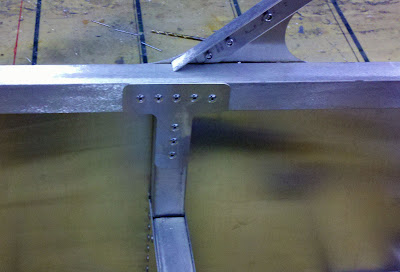
Side T Gusset riveted in place.
Please make sure you've placed clecos in the rear tube, as shown below:

Clecos on rear tube
Gussets need to be added on each Rear Diagonal Support.  A bend is placed in each gusset prior to placement.
Rear Gusset for Rear Diagonal Supports.

Another view of gusset for Rear Diagonal Support, clearly showing bend
Rivets on the gusset
Ensure that rivets have been placed on the bottom of the rear fuselage.
Rivets on bottom of rear fuselage.