Please note: James' blog has moved to a Wordpress site. To access it, please visit http://jameswiebe.wordpress.com/. All posts have been transferred to the new site, and all new posts will only be accessible via Wordpress. Thank you for your interest!
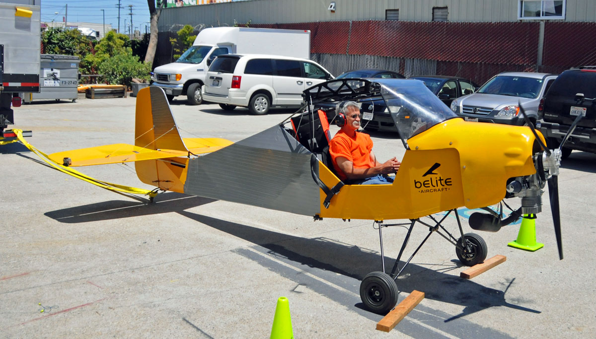
Ultralight Airplane Flaperon Assembly Manual for Belite Aircraft
Ultralight Airplane Flaperon Assembly Manual for Belite Aircraft
Last Revised November 28, 2011

Figure 1 Completed Flaperon, on a plane.
Photos © 2011 by Gene Stratton and James Wiebe.
© this document 2011.
SPECIFICATIONS:
·
CERTIFICATION STATUS:
NONE. THESE FLAPERONS ARE
UNCERTIFIED. Use only on experimental or
ultralight aircraft, at your own risk.
·
CHORD:
12” (0.305 meter)
·
LENGTH:
105 ¼” ( 2.673 meter) (span of single flaperon, excluding mounting horn
extension)
·
AREA (per flaperon): 8.77 square feet (0.815 square meters)
·
WEIGHT:
dependent on amount of paint and glue.
About 4 pounds.
·
RED LINE Vne:
80mph. Do not use these flaperons
on aircraft exceeding 80mph.
·
CAUTION:
62mph is top of green arc. Keep
flaperons centered (0 degrees relative to chord of main wing) and make only
slight movements at 62mph and higher.
MATERIALS:
·
MAIN SPAR:
0.875” x 0.035” 6061-T6 round aluminum, one piece for each flaperon.
·
LEADING EDGE:
0.500” x 0.035” 6061-T6 round aluminum, one piece for each flaperon.
·
TRAILING EDGE: 1.125” preformed 3003 aluminum
(Aircraft Spruce PN: 03-48900), one piece for each flaperon.
·
MAIN RIBS:
Precut 1/8” Birch Plywood, qty 28 (14 per flaperon)
·
FALSE RIBS:
Precut 1/8” Birch Plywood, qty 56 (28 per flaperon)
·
NYLON BUSHINGS:
fits over main spar and in flaperon droppers. Qty 6.
·
MACHINED ALUMINUM DROPPERS: fits to nylon bushings, allows attachment to
your wings. Qty 6. Machined from aluminum. Parts are “heavy duty”, having replaced an
earlier design which wasn’t as beefy.
·
CONTROL HORNS:
One for the left and one for the right dropper. Made from welded steel.
·
RIVETS:
Qty 8, use four to connect each control horn.
·
ALUMINUM SHEET:
0.016” thickness, Qty 16, use to create ‘boxes’ at each end of flaperon,
also around flaperon machined droppers.
·
BALSA WOOD:
used to create rounded end on far end of each flaperon. You should have
24” of 1x1” balsa. Makes two end caps.
·
NUTS, BOLTS, and WASHERS (used to attach
flaperon to wing). Qty 12 of each.
·
BLUEPRINTS in electronic form – you print. We can email these to you.
·
MANUAL (this document) in electronic form – you
print. We can email this to you.
NOT INCLUDED:
·
GORILLA GLUE
·
WOOD SEALANT such as exterior polyurethane
·
FABRIC COVERING and associated materials (fabric
glue, primer, paint…)
·
CLEANING SUPPLIES (sandpaper, scotchbrite,
acetone…)
·
TOOLS (normal stuff like clamps, pliers,
aviation metal snips, riveters…)
WORK AREA:
·
You will need a work area, completely flat,
allowing you to build a flaperon. A
minimum size of 18” by 10 feet is recommended.
CHECK YOUR MATERIALS:
·
In the event that
you have any shortages, you MUST notify us within 14 days of receipt of this
kit.
1. Preparation.
a) Ensure
that your work area is absolutely flat and big enough (10’ x 18”).
b) Read
these instructions through at least three times before doing anything. Ensure you understand everything before doing
anything!
c) Remember,
you are building a LEFT and a RIGHT flaperon.
Please don’t build two left flaperons (or two right flaperons).
d) Remove
plastic film from trailing edge material.
e) Clean
up all aluminum using scotchbrite and acetone, as required.
f) Trim
and sand all plywood parts to finished shape.
(Remove the excess tabs). Check
that they fit over the spar tube, and that the leading edge tube also fits in
the front notch of the rib. Sand as
necessary. We like using a round drum
sander, such as are commonly used with a Dremel or electric drill.
g) Ensure
that nylon bushings fit over spar.
Ensure that they also fit inside machined droppers. Sand inside and outside of nylon bushing as
necessary. Final fit should be ‘butter
smooth’. Absolutely no friction
allowed. Flaperon dropper should flop
and swing under its own weight. IF YOUR
NYLON BUSHINGS ARE “OVERSIZE”, YOU MAY NEED TO MOUNT THE NYLON BUSHINGS IN A
DRILL CHUCK AND TURN THEM DOWN TO THE CORRECT DIAMETER USING A MILD RASP OR
SANDPAPER.
h) BEFORE
YOU GLUE ANYTHING, make sure the surface is roughed up with sandpaper and
absolutely, completely clean with acetone.
This is absolutely necessary to get a good glue bond to aluminum.
i)
A note on Gorilla glue:
Our design has all of our ribs ‘locked’ in place by design, and the glue
further immobilizes them. This is true
in our flaperons, and also in our wing design.
We use Gorilla glue in some locations because it adheres to materials
extremely well, and because it is not used as a structurally critical bonding
material. Also, Gorilla glue expands
enormously, so use sparingly. Read the
instructions on the glue container. We
like to have water available in a misting bottle, so that it can be sprayed
lightly on components which are to be glued.
2. Test
Fit Ribs and Bushing/Droppers
a) DON’T
GLUE ANYTHING until specifically instructed.
b) Slide
all of the ribs, false ribs, bushings (with droppers) onto the spar. Sand out the holes as required. Remember, each rib has a top and a bottom,
because the airfoil is not symmetrical.
c) Using
the blueprints as a dimensional placement guide, determine where to place all
parts. You may wish to place tape on
your bench to mark locations, as shown in our photos.
d) *******
NOTE *******, although not shown in our photos, place an extra false rib on
each side of the flaperon droppers, at approximate locations of 46”, 47 ¼”,
93”, and 94 ¼”. These will help you when
it comes time to glue aluminum sheets on the top and bottom of these box
locations. If you forget to put them in
now, they are tough to get in later.

Figure 2 Sliding the Ribs over the spar

Figure 3 Another view of sliding the
ribs over the spar
3. Glue
the Main Ribs
a) MAKE
SURE you have all parts slid over the spar and properly oriented. If you forget them now (or have them upside
down) it is very hard to fix later.
b) GLUE: the main spar to the main ribs. Clamp the main ribs to the work bench, as
shown in the photo. We use a glue
syringe and minimal amounts of Gorilla brand glue. MAKE SURE that everything is absolutely
square. Allow glue to set.

Figure 4 Clamping the main ribs to the workbench
4. Glue the Leading Edge, False Ribs
a) Clamp
the leading edge (0.500” round tube) to the flaperon assembly, as shown in the
photos. This locks all of the main ribs
and false ribs in position. Make sure
everything is absolutely square. You can
hang the assembly off the end of your bench, as we show in the photos.
b) GLUE: the leading edge into position with Gorilla
glue to all ribs. Also glue the false
ribs to the main spar.

Figure 5 Gluing the leading edge, false ribs, and main
ribs

Figure 6 Letting the flaperon hang from supports while
gluing leading edge
5. Trailing Edge
a) Using
a flat pliers, smash the trailing edge material so that it matches with the
locations of the main ribs. See the
photos. Don’t use a pliers with
serrations, as it will scratch your aluminum.
b) ENSURE
that the insides of the trailing edge are substantially roughened, wherever it
mates with a rib. You’ve got to do a
good job of roughening, so that the trailing edge will remain glued in place.
c) GLUE
the trailing edge into position with Gorilla glue.

Figure 7 Trailing edge showing 'smash' detail

Figure 8 Trailing edge being fitted

Figure 9 Trailing edge being glued
6. ‘Box’
Fabrication.
a) Each
flaperon is boxed at four locations, using aluminum sheeting: at each end of the flaperon, and at the two
locations where the flaperon droppers are attached. The boxes are composed of a top sheet and a
bottom sheet.
b) Make
sure the aluminum sheets are of the right size.
Make sure the slots (for the droppers) are cut to fit. Trim as necessary.
c) ROUGHEN
and CLEAN the aluminum sheets, so that the glue will adhere.
d) Glue
into position.
e) ABSOLUTELY,
POSITIVELY DO NOT allow glue to get close to the nylon bushings and droppers.
f) We
built our units without rivets on these box structures. You may choose to use rivets along the
attachment to the trailing edge, if you desire.

Figure 10 Tip box skin glued and clamped

Figure 11 Tip box after clamps removed, before clean up
and trimming

Figure 12 Another view of tip box, top down (Excess spar to be cut off)

Figure 13 Root box.
Don't cut off the root spar!
7. Trim ends of flaperons; trim glue.
a) If
your spar, or trailing edge, or leading edge extend beyond the outside rib,
trim them flush using a band saw (or hacksaw).
Sand smooth. DO NOT trim off the
main spar on the inside rib – you need this ‘root’ section to install the
control horns.
b) Sand
off all excess glue. If you were neat
with your glue application, this is not a big problem.
8. Attach Balsa end blocks
a) Glue
a piece of balsa to outside end of flaperon.
Use gorilla or wood glue.
b) Carve
and sand to produce a pleasing aerodynamic appearance.

Figure 14 Balsa end cap, carved and sanded.
9. Apply sealant to wood.
a) Spray or brush on two coats of a good weather
resistant wood varnish on all wood surfaces.

Figure 15 Protect the wood by giving 2 coats of
exterior varnish.
10. Covering.
a) Cover
with lightweight dacron fabric, prime, and paint.
11. Check
Fit to wing assembly; install control horns.
a) After
you have assembled the wings, clamp the flaperon droppers to the wing assembly
to check fit. Slight adjustment of wing rib
placement may be done to compensate for fit.
b) BEFORE
INSTALLING CONTROL HORNS, ENSURE that wings, when folded, allow control horns
to overlap. This is a tricky and
critical step. Slight offset of control
horns allows this. This means you must
build the wings, and test fit wings on the fuselage, before installing control
horns!
c) After
test fit is complete and perfect, install control horns using four rivets
(supplied) and 3M 2216 glue (not supplied).
Control horns are to be placed 90 degrees perpendicular to flaperon
chord.

Figure 16 View of uncovered flaperon in test fitting to
wing (NOTE: aluminum box structures not yet done)

Figure 17 Another view of uncovered flaperon
(NOTE: aluminum box structures not yet completed)

Figure 20 Quartering view of full left flaperon

Figure 21 Root of right flaperon after installation.
********************************************************