Monday, March 18, 2013

Construction of Tail Feathers

Please note: James' blog has moved to a Wordpress site. To access it, please visit http://jameswiebe.wordpress.com/. All posts have been transferred to the new site, and all new posts will only be accessible via Wordpress. Thank you for your interest!


Aerodynamic Tail Feather construction for a Belite

We'll cover both pieces of our horizontal tail assembly in this document:  the elevator, and the horizontal stabilizer.

Construction of both pieces is very similar.  Please refer to the blue prints for layout dimensional information.

Prior to assembly, all wood pieces are sanded and deburred.  Steel and aluminum pieces are cleaned.  Steel pieces are also painted, except where glue joints will be.  (We cover the steel pieces with strategically placed masking tape, then spray paint is applied.)

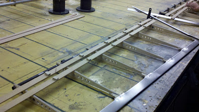
Let's start with the elevator.  We use 3M 2216 glue to attach the wood ribs to the elevator spar.  We also glue tail end gussets to the end of each rib using high quality wood glue.

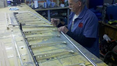
Elevator Assembly already under way.
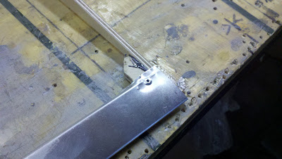
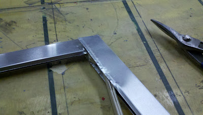
The trailing edge is fitted into place.  It will fit snugly over the wood ribs and gussets.  The trailing edge usually has a plastic film both inside and outside; remove the film.

Trailing edge being fitted over elevator.
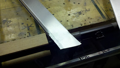
Still checking fit of trailing edge.
Trailing edge cut to length.
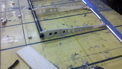
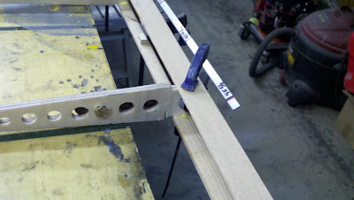
Now it is time to install the four bolts, one on each torque arm.
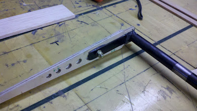
Bolts added.
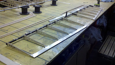
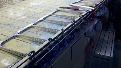
Use rivets to hold the trailing edge in place.  Rivet washers are also used on the underside.

Trailing edge riveted in place.
The wood strips are prepared by gluing in spacer blocks.

Wood strips and spacer blocks, glued together.
The wood strips are then glued to the wood ribs.

Wood strips glued to wood ribs.
Closeup of clamping detail.
Two pieces of trailing edge material are cut to fit in the center section.
Preparing the center section trailing edge.
More preparation.
Glue the balsa block on each end.  Make room for the top of the bolt.  Also, unlike shown below, it may be helpful to pretrim the outline of the rib in the balsa.

Balsa block glued.
 The center section must also be riveted in.

Riveting in the center section trailing edge.
Adding more paint.
Alternate viewpoint.
End balsa cap, ready to be rough cut to shape and sanded.
Insulating Foam injected around blocks to add stiffness.  Trimmed flush after setting.
Center section cleaned up very nicely.
 After everything is sanded, apply at least two coats of varnish before covering.

Varnish the wood!

 Next, we'll finish up the horizontal stabilizer.

TO BE CONTINUED....


Monday, March 11, 2013

Customer Cabin Pics

Please note: James' blog has moved to a Wordpress site. To access it, please visit http://jameswiebe.wordpress.com/. All posts have been transferred to the new site, and all new posts will only be accessible via Wordpress. Thank you for your interest!


A customer sent me a couple of nice pics of his cabin assembly, in progress.

Belite Ultralite Aircraft Cabin Assembly

Belite Ultralight Plane Cabin Assembly

Wednesday, February 27, 2013

Floats, Tricycle Gear, Turtledeck, Builder tips

Please note: James' blog has moved to a Wordpress site. To access it, please visit http://jameswiebe.wordpress.com/. All posts have been transferred to the new site, and all new posts will only be accessible via Wordpress. Thank you for your interest!


Something for everyone...

One sneek picture of an amphibious float is somewhere below...

Pics of the Sky Blue plane with a turtledeck on it, builder tips for those builders seeking help, photos of a tricycle gear fuselage under construction, photos of a primed fuselage, carbon fiber spars, all for the ultralight Belite Aircraft.

By the way, my heart goes out to designers of amphibious floats.  Hardest design project, ever.


Carbon fiber spar with jury strut fitting.  Wrapped with carbon fiber rope and epoxied.

Sky Blue Ultralight Belite with turtledeck.

Another view of the sky blue ultralight Belite Aircraft.

Blurry picture of lift strut fitting, with carbon fiber rope and epoxy.

Messy job on the glue, but aluminum doubler (2.75" OD) over carbon fiber spar.  Tripler on inside root.

New design Belite door.  Coolest ultralight aircraft door, ever.

CNC cut frame on inside of door frame.  Note two pins for locking door closed.

We added corner pocket windows to this Belite.  Edge of  polycarbonate door panel is visible.

This side of the plane has a polycarbonate window installed.  Easily removable 'cuz we used Nutserts.

Swing the door up.  Someone really ought to add a gas lift strut.

Door hinge installed on top of door.


Picture of amphibious float.  How'd this photo slip in here?

Really bad photo showing one way to overlap fit trailing edge material together.

Another way to fit trailing edge together.  Works with wood ribs if you use a left and right gusset.

Tricycle gear airplane under construction.

Finishing tail of tricycle gear airplane.

Underside of rear deck, showing structure. 
Gusset detail on tricycle gear airplane. 

More gussets.

This gusset is doubled, as gear hinge will be bolted here.

And here as well.  Doubled.

Another view of the bottom of the rear deck.

View of the front.  Nose gear not yet installed.

Detail of front of fuselage.

Detail of front of fuselage.

Some aluminum primer, some paint.  This bird nearly ready to cover.

Monday, February 25, 2013

Retractable Gear Assembly for Amphibious Ultralight Float

Please note: James' blog has moved to a Wordpress site. To access it, please visit http://jameswiebe.wordpress.com/. All posts have been transferred to the new site, and all new posts will only be accessible via Wordpress. Thank you for your interest!


We are in the middle of a blizzard here in Wichita, KS.  So we all left work early, and I brought home a prototype wheel assembly for our ultralight amphibious float.  It needs a slight bit of tuneup, but I figured you'd like to see the engineering work in process.

ultralight aircraft landing gear
Main retractable landing gear for ultralight amphibious float.

Front view of retractable gear assembly.

View of reverse side of retractable landing gear.

The wheel used is a 5"; the brake assembly is an Avid BB5.  Assembly is not complete.  Weight of the entire subassembly will be about 7.5 pounds per assembly.