Monday, January 7, 2013

Belite Aluminum Ultralight Aircraft Cabin Construction, #8

Please note: James' blog has moved to a Wordpress site. To access it, please visit http://jameswiebe.wordpress.com/. All posts have been transferred to the new site, and all new posts will only be accessible via Wordpress. Thank you for your interest!


This is series #8 in our Belite Aluminum Ultralight Aircraft Cabin Construction articles.

It's back to work on the aluminum cabin for a Belite ultralight airplane!  We're going to be working on the internal details now.

BTW, your cabin should now be covered.  You'll need to take care as the cabin is worked on, in order to not tear or scratch the dacron fabric.  This is critical because you'll be slitting the fabric and mounting the landing gear center brace through the fabric.

We've taken the liberty of additionally covering our cabin  with turquoise Oracal, which is our fantastic covering method.

Our two tasks today are closely related:  we'll mount the landing gear cross brace, and we'll build and mount the control stick mount box.

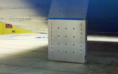
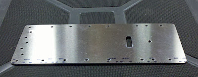
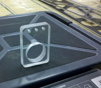
There are two landing gear cross brace plates.  They look like this:

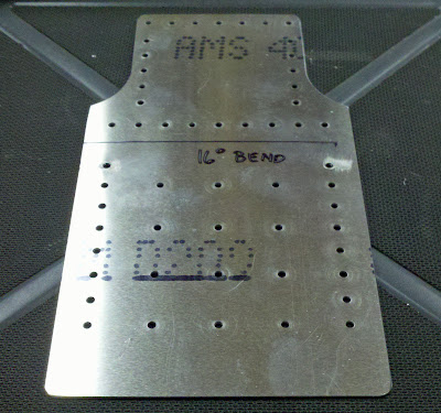
Landing Gear Cross Brace Plate for Belite Ultralight Aircraft.

After bending each piece, and slitting the fabric on the bottom of the cabin, the pieces are inserted through the slits and riveted in place.

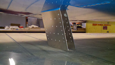
Landing Gear Cross Brace Plates inserted through slits in fabric
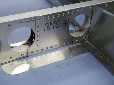
Landing Gear Cross Brace Plate riveted in place
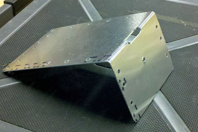
Two short pieces (approximately 4 1/4") of 3/4" thin wall square tubing are cut in place and clamped, as shown in the photo below.


Landing Gear Cross Brace Plate with tubes clamped in place.
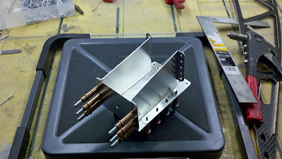
Rivets in place on Landing Gear Cross Brace Plate
another view of Landing Gear Cross Brace Plate
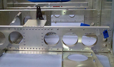
 Now collect the three pieces of metal which comprise the control stick support box.  
Control Stick Support Box sides
Control Stick Support Box top.
Side with tabs bent.   Use a brake, or a vise, or wide jaw pliers, or helpful friends.
Top with bend
Box with clecos.
Box with rivets.

Box clecoed to cross box.
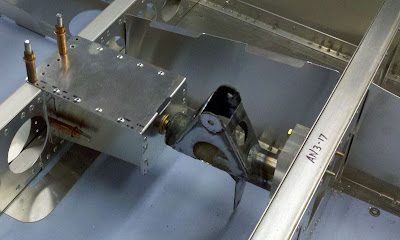
 Note that in the following photo, the steel pivot arm has appeared.  You'll want to check fit with it very thoroughly before riveting, as the instructions for its mounting follow!  Also note that the attachment bolt is an AN4-7 with washers and a locknut.

Box riveted to cross box.
 So let's investigate what needs to be done to attach the steel pivot assembly.

Bearing for pivot assembly.

Bearing bolted in place with two AN3 bolts.  Do not overtorque!
Closeup of AN3-17 bolts used to attach bearing.

Test fit.  

 The control stick pivot should rotate with complete freedom.

Another view of assembly, complete.


Tuesday, January 1, 2013

Belite Aluminum Ultralight Aircraft Cabin Construction, #7

Please note: James' blog has moved to a Wordpress site. To access it, please visit http://jameswiebe.wordpress.com/. All posts have been transferred to the new site, and all new posts will only be accessible via Wordpress. Thank you for your interest!


In our continuing series of aircraft construction articles, it's time for a photo review of the cabin assembly prior to covering.

Front Diagonal Support / Star Gusset area
Front view of cabin assembly.
View of Floor Pans, front assembly near firewall, first cross box.
Another view of floor pans and first cross box.
View of internal cabin assembly.  Baggage compartments on left side of photo.  Pivot location has been drilled and nylon 3/8" bushing is clearly (but barely) visible.
Lucky focuses on food.  Windshield support.
Cabin assembly from side.
Top gussets.
Nose of cabin assembly.
Top of cabin assembly.
Chance checks the weight of entire cabin assembly:  22.4 pounds
It is now time to cover the cabin assembly with dacron fabric.  Construction of the interior details of the cabin continues after you've covered the cabin assembly.

Belite Aluminum Ultralight Aircraft Cabin Construction, #6

Please note: James' blog has moved to a Wordpress site. To access it, please visit http://jameswiebe.wordpress.com/. All posts have been transferred to the new site, and all new posts will only be accessible via Wordpress. Thank you for your interest!


#6 in the series.

We will start by attaching the rear fuselage attachment gussets.  There are six:  two on each side, and two on the bottom.  The top side gussets, the bottom side gussets, and the bottom gussets are each unique.  They may vary slightly from these photos in appearance, due to fit and lightening improvements.  Fit, cleco, and rivet them in place, as shown in the following photos:

Bottom Side Gusset and Bottom Gusset, clecoed in place
Bottom Side Gusset, riveted in place
Top and Botom Side Gussets, riveted in place
Bottom Gusset, clecoed in place.
Rivet all six gussets in place.

Now we will work on attaching the 'sun roof skin' to the top of the cabin.

The front vertical pieces are marked and cut off with a dremel tool.
After cutting off the vertical angle aluminum supports, we can add in the two cross tube supports, which were are cut from 1" 6061T6 .063 square tubing.

6061T6 1 x 1 x .063 cross bars.  Cut to length shown.

We will also add in the 1" thinwall tubing, which runs along the top of top door skin, and is shown clecoed in and clamped in place in the following photo.   They are simply cut to fit.

All top cabin tubing shown
Top skin clecoed in place.
Another view of top skin clecoed in place.
Small inside gussets for top of cabin.
Riveting the top sunroof skin in place.
Closeup of corner of top skin.
You'll need to make a bend in the windshield support.

Windshield support with bend.
Windshield support clecoed in.
Windshield support riveted in.
Now it's time to cleco in the remaining baggage compartment dividers.

Pay attention:  the tabs may be bent either way, but only one way is correct.  Study the parts, your assembly to date, and all of the photos to ensure that you do it correctly.  The tabs are easily bent in any brake or even with a bench vise.  There are also hand tools which make them easy.

Baggage compartment divider.

Baggage compartment dividers in place.
Note that the bottom skin is not entirely pre-drilled.  This allows you to fit the best alignment on your baggage divider skins and under the front floor pan (which may require you to drill out a few rivets to fit under).

Bottom skin, ready to install.

 Bottom skin clecoed in place, fit under floor pan and under landing gear gusset.

Bottom skin partially riveted in place.
Rear Landing Gear gussets clecoed in place.
Fabric trim plate for bottom landing gear cross attach post.
Fabric trim plate riveted in place.
Front Diagonal Support gusset, bent and riveted in place.
Front Diagonal Support gusset, riveted in place.
Doublers at engine mount area
Doublers at engine mount area, riveted in place.

Top of cabin, ready to accept gusset.
Bent gusset.
Gusset riveted in place.  One of these rivets will be drilled out.
 One of the rivets will be drilled out in order to accept the "X" steel cross brace.

NEXT:  PHOTO REVIEW OF THE CABIN ASSEMBLY, PRIOR TO COVERING.