By James Wiebe
Brief Introduction of James Wiebe
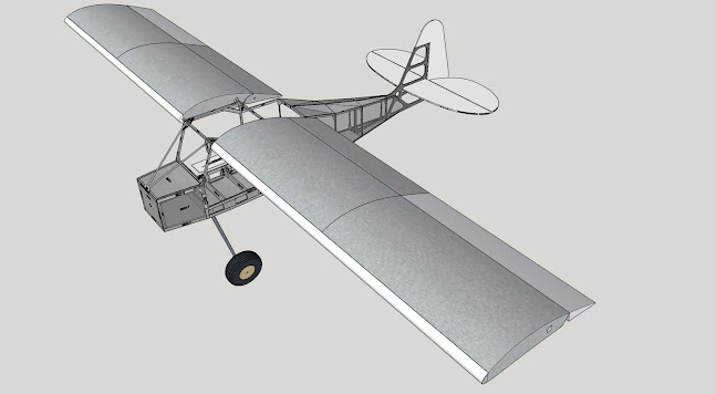
I am the CEO of Radiant Technology, with 45 years of varied management and electrical engineering experience. I am also a passionate pilot and serial entrepreneur. I am highly skilled in sensor design. A recent accomplishment which I am proud of was an airborne logging sensor package, done as a subcontractor on a USAF contract.
Goal of this White Paper
In this paper, I am discussing the use and design factors in Carbon Monoxide detectors, monitors and alarms, hereafter referred to as "CO Detector". Use discussion of CO Detectors includes the background need along with the application of these devices. I also dig deeply into design and implementation issues. I provide comments as these factors relate to our new product, "CO Pro".
The Need for CO Sensors
Aircraft accidents caused by CO poisoning have documented by the FAA and by the NTSB. The FAA has prepared a helpful online brochure which is available at the following link:
Where the FAA shares the accident of a Piper Comanche 400 piloted by Dr. Robert Frayser. The accident resulted after he'd taken off and was flying from North Bend, KS to Topeka, KS. In dramatic fashion, he awoke inside his wrecked aircraft in a hay field, thinking he was still in cruise flight. In actuality, he had been poisoned and incapacitated by CO. He was fortunate to be alive.
Dr. Frayser was taken by ambulance to a hospital, where the emergency room physician put him on 100 percent oxygen to overcome near-fatal blood levels of carboxyhemoglobin. Another 30 minutes might have been fatal, given the high dose of CO exposure he received. Please read the full FAA article.
The FAA includes the following advice:
"Carbon monoxide poisoning is a safety issue that pilots tend to ignore, even though it is the most common industrial poisoning accident in the United States. When carbon monoxide poisoning occurs, it can have significant and fatal consequences for aircraft occupants."
The NTSB has also published Safety Alerts for avoiding CO poisoning. In SA-069, they cite four different aircraft accidents caused by CO. They make several conclusions, one of which is:
"Install a CO detector and replace the device and its batteries in accordance with manufacturers’ guidelines. Detectors mounted on the instrument panel with aural alerts and a flash notification are more likely to draw your attention and alert you to a potential hazard."
For the full NTSB Safety Alert 069 and all of their recommendations, please follow this link:
NTSB Safety Alert 69 / Pilots: Prevent Carbon Monoxide Poisoning
Clearly, the FAA and NTSB recommend pro-action on avoiding CO poisoning, with good planning including the use of a CO detector combined with a plan for the pilot to follow when CO is detected.
Design factors for an Airborne CO Detector
Before I begin, I will make one observation: many pilots have installed a stick-on CO detector which changes color during CO exposure. I hate them and think they may cause more harm than good by creating a false sense of security. I have flown in aircraft which had them affixed; almost certainly aged out and worthless. They do not flash or make a sound. They are easy to ignore. Their failure condition (age) is easily overlooked.
The NTSB and FAA's thought processes do not dig deeply into what makes a good CO detector. Missing in their recommendations are qualifications on accuracy, linearity, aging, indications, and so forth.
I propose the following questions, as part of the design process and user selection criteria. I discuss each one in turn, especially as it relates to the design process of my premium CO detector, CO Pro .
a) Does the sensor within a CO detector degrade over time, and if so, what is some data thereto?
Yes, sensors do degrade. For a good sensor, this degradation can be measured in many years or even, potentially, in decades. (The stick on detectors have a lifespan of 12 months.) CO sensors are commonly based on electro chemical designs. This means that the CO sensor has chemical elements within it that change an electrical value (for example, extremely minute amounts of electrical current) in response to higher levels of CO. Here is a chart provided by my selected sensor manufacturer which shows real degradation of the sensor over a period of one year.

Yes, all sensors have limiting factors, such as heat or saltwater exposure. For my product, these conditions are well understood, declared and practicable in operation. Here they are:
- Condensation and Water
- Salt Water Contamination
- High Temperature Operation (> 70C) for more than 1 month
- Low Humidity Operation (< 15% RH) for more than 3 months
- High Bias voltage
- Highly contaminated air over a prolonged period
- High levels of particles or soot (unless proper filtering is provided)
- The product is not designed to be wet or used in rain or in moisture condensing conditions.
- The product is not designed to be exposed to sea spray or any salt water.
- The product is not designed for use anywhere near 70 degrees C (158 F)
- The product is not designed to be used or stored in extremely dry air for more than 3 months
- The bias voltage is a technical design issue. I designed my sensor with a bias voltage of zero volts. This allows the sensor to always be available for use; which allows me to claim the Always On feature of our product.
- The product is not recommended for continuous use in highly contaminated areas. If you are in bad air, get out, and take the CO Pro with you.
- The product will eventually degrade or fail if exposed to high levels of particles or soot.
It should. For CO Pro, there is a "linearity" adjustment which is easily reached by the user. The user may change the linearity setting at any time. To do this in a meaningful way, the device is placed in a calibrated chamber, the reading on the device is observed, and thereafter, the linearity setting is changed by the user or the test lab.
d) Does the CO detector allow for immediate recalibration related to zeroing?
It is likely that the CO sensor used within an airborne CO detector will have very minimal localized drift around the zero point. This may be resolved in several ways: by an automatic device calibration, a manual calibration. In CoPro, I offer two solutions: automatic calibration or user zero point calibration on demand, anytime. Using automatic calibration, any drift is detected and zeroed out. Manual zero point calibration is also always available.
In some types of CO detectors, the sensor itself contains a tiny heater. These require a considerable period of time to get to operating temperature. They also use more battery power, but they resolve zeroing issues by performing it automatically after the sensor is heated. This type of detector will be subject to degradation over time.
e) Does the useful life of the baseline sensor extend beyond 5 years?
This question, along with battery life, are the most common questions from CO detector purchasers. The answer varies by sensor design, of course.
For my product CO Pro, per the base sensor manufacturer, the expected operating life is greater than 5 years. More specifically, once again per the sensor manufacturer:
"The working electrode functions as a catalyst for the electrochemical reaction of the analyte, but is not itself reacted or consumed. Thus, under ideal conditions, the sensor will exhibit a stable response for an indefinite period of time. For typical indoor environmental conditions (23 ± 3 °C, 50 ± 20% RH), a 10 year operating life is expected. Our current long term testing has shown a failure rate of < 1.3 failures per million hours of operation (FPMH). Expressed differently, this illustrates a minimum mean time between failures (MTBF) of >790,000 hours (>90 unit-years!) cumulative operation. For these tests, failure is determined by the UL2034 sensitivity requirements."
f) Is there a service life history of the part and / or our product which verifies these assertions?
I rely on the assertions of the CO sensor manufacturer which I have chosen. As most products in the aviation market were introduced in the last 5 years, our standing is likely to be similar to other device manufacturers.
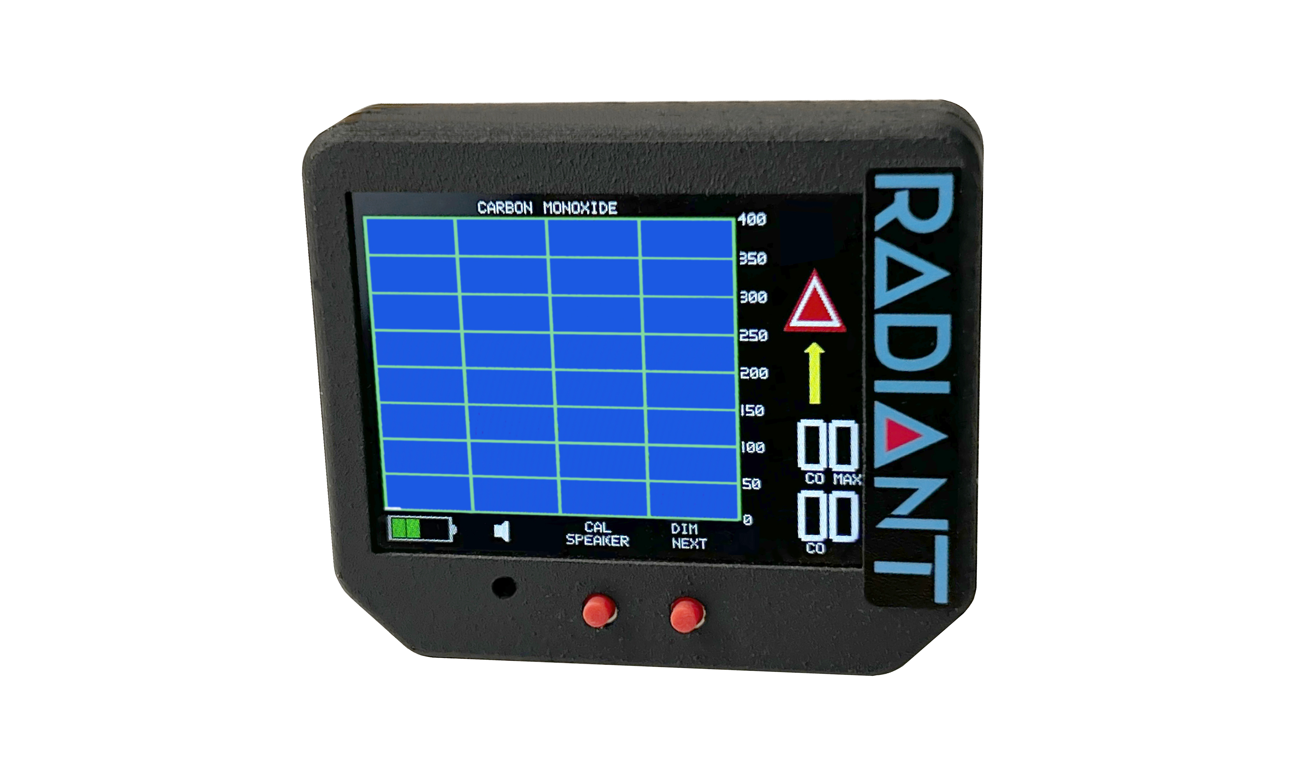
g) Does the unit provide a visual and aural alert? If so, what does the alerts entail?
Every unit on the market provides information via some sort of visual indicator: The black and white LCD screen is the most common.
I chose a full color screen instead. This allows warning information to be shown in several ways:
- Graphing over time
- Current PPM calculation which changes color and value as CO levels rise
- Maximum PPM value which is also color coded
- Arrow Alert points upwards when CO level is rising; it blinks and is color coded with yellow and red
- Hazard Alert illuminates at critical (100PPM) CO levels; it is presented as a standard red hazard icon.
- Battery Level
- Speaker on / off icon (for muting active aural alarms)
- Screen is dimmable for nighttime use.
- Aural alarm sounds when value is reached (default: 50 PPM)
The screen display is daylight readable, bright and clear.
h) May the battery be replaced by the user?
If the CO detector uses a fixed (nonrechargeable) battery, it must be replaced as recommended by the manufacturer or when the battery is low, whichever occurs first.
If the CO detector has a rechargeable battery, then it must be recharged. How? For CO Pro, we provide a power only USB port, allowing the CO detector to be recharged.
Every time the power on the unit is turned on, I log a power cycle. This is briefly shown as the unit powers up. Radiant recommends the replacement of the rechargeable battery after 1000 cycles.
The battery is accessed by removing a sticker and two screws.
i) After power up, how long until the CO detector is ready for use?
i) After power up, how long until the CO detector is ready for use?
Some are nearly instantaneous; others take up to a couple of minutes. In the case of CO Pro, the turn on time is about 10 seconds. Due to the engineering of the unit including the aforementioned Always On circuitry, the unit does not require any heater warm up time.
j) What about cross sensitivities to other gases?
The CO detector manufacturer should be able to tell you what other gases the detector is sensitive to.
The CO detector manufacturer should be able to tell you what other gases the detector is sensitive to.
For CO Pro, the cross sensitivities are as follows:

This means that CO Pro reacts with Hydrogen, Carbon Monoxide, and very slightly to Alcohol.
k) What about secondary functions of the CO detectors?
Significantly, LightSpeed is selling headsets with built-in CO monitoring, and we are introducing CO Pro with a secondary function as well: G-Meter. The thought process behind this was fairly simple, and was approached from a marketing perspective. Since the CO detector normally is doing very little (reporting continuously @ 0 PPM CO), why not make a useful secondary function? I did this by including the G-Meter. Most aircraft do not have one; most pilots and some passengers want to know how strong the bumps were. The G-Meter is presented in a classic dial format:

The CO levels are shown continuously on the G-Meter screen. Should CO levels rise, CO Pro switches automatically back to the CO graphing screen.
Summary of Use and Design Factors in CO Detectors
I have reviewed the FAA and NTSB guidance and provided links to their documents. The NTSB recommends the use of a CO detector in aircraft.
I have asked these critical questions:
b) Are their conditions which would adversely affect the sensor, and if so, what are they?
c) Does the CO detector allow in situ recalibration for overall sensor changes (degradation) over years of time?
d) Does the CO detector allow for immediate recalibration related to zeroing?
e) Does the useful life of the baseline sensor extend beyond 5 years?
d) Does the CO detector allow for immediate recalibration related to zeroing?
e) Does the useful life of the baseline sensor extend beyond 5 years?
f) Is there a service life history of the part and / or our product which verifies these assertions?
g) Does the unit provide a visual and aural alert? If so, what does the alerts entail?
h) May the battery be replaced by the user?
i) After power up, how long until the CO detector is ready for use?
j) What about cross sensitivities to other gases?
k) What about secondary functions of the CO detectors?
And I have provided answers as it relates to any detector, or more specifically the design of CO Pro, a CO detector from Radiant Instruments.
If you have questions or background material which you believed I've missed, please drop me an email.
I hope you've enjoyed the read.