Please note: James' blog has moved to a Wordpress site. To access it, please visit
http://jameswiebe.wordpress.com/. All posts have been transferred to the new site, and all new posts will only be accessible via Wordpress. Thank you for your interest!
This is the final installment in the Belite Aluminum Cabin Construction.
As I mentioned last time, we've got a short list of items to go. Let's cover these last items. (This doesn't include options such as doors or windows; optional items will be covered another time.)
This is what we have left to do:
A) Finish riveting in the small seat.
B) Construct and fit the main seat.
C) Install the bottom strut attach reinforcement bars.
D) Attach the seat belts. We don't supply the seat belt, but an example installation is shown.
E) Attach the fuel tank. As we do not supply a fuel tank, an example installation is shown.
F) Attach the wings.
G) Attach the top cabin windshield ribs.
H) Attach the windshield.
Let's get going.
A) After thoroughly checking all underseat fittings and hardware, rivet in the small seat. Use 3/16 rivets on the front and back.
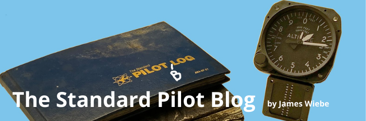
B) The main seat bottom and back are pre-cut, and are supplied elsewhere in your kit. We recommend riveting the bottom and back using scrap material. As an alternative, consider using a hinge (NOT INCLUDED IN KIT) and preparing as follows.
Rivet hinge material to the bottom and back. Also rivet three lengths of angle aluminum to the back of the seat.
 |
| Closeup of hinge. |
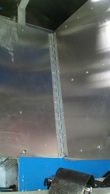
I'm sorry I don't have a better picture of the back seat, showing the reinforcement riveted to the rear. The rivets are visible in most of these photos.
 |
| A hinge is riveted to the bottom and back. |
Use nutserts (rivets that contain nuts) in four locations on the bottom, so that the seat may be attached and removed easily.
 |
| Four nutserts hold the bottom seat down. They are hard to see. |
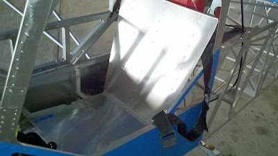
Install trim along top edge to prevent problems with the sharp edge.
 |
| Back of seat, showing rivets and trim along top edge. |
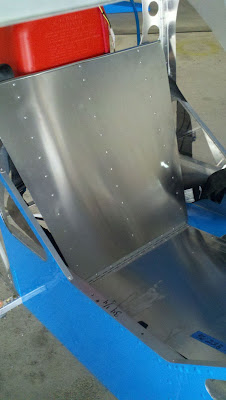
 |
| Another view of top of seat. |
 |
| Seat folded forward, showing access to potential additional baggage compartment below fuel tank. |
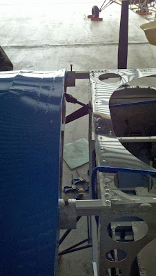
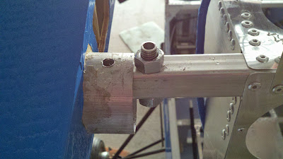
C. Install the bottom strut reinforcement bars and Y strut.
2 reinforcement bars are included with the kit. You will need to drill them out as follows:
 |
| Reinforcement bars, showing drill locations. |
 |
| Place Y strut fitting over bottom tube. Drill. |
 |
| Drill to match reinforcement. Install bolts. |
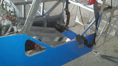
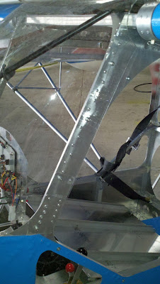
D. Attach Seat Belts.
Seat belts are NOT supplied with the kit. We recommend using a four point seat belt. The seat belts are attached as follows. Install reinforcement angle aluminum to the lower attachment points:
 |
| Seat belt lower attachment point, showing angle aluminum reinforcement. |
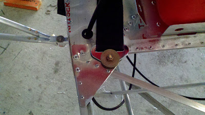 |
| Upper Seat Belt attachment point. |
 |
| Another view of upper seat belt attachment point. |
E. Install fuel tank.
We use inexpensive 5 gallon plastic tanks. They are available in various shapes, I constructed a metal flange on my shopbot to match the bottom of the tanks we are currently using. We've also used aluminum angle for the same purpose. As can be seen below, the flange was riveted to the deck and then straps were used to secure the tank (more than shown in the photo, below).
The fuel line was run to a quick disconnect fitting, the tanks was vented, and it was quickly ready to fly.
 |
| Fuel tank installation. |
Fuel tanks may also be installed below the deck. Also, we've used a lot of aluminum tanks, and they look great too!
F. Attach the wings.
The following rules MUST BE FOLLOWED:
1. The cabin must be leveled left / right and fore / aft. This means that taildraggers have to have the tail lifted off the ground.
2. Remember, the hangar floor is often unlevel. Use a water level to verify that the wingtips are level to each other.
3. Wings should have 3 to 4 inches of dihedral. This is tested by running a line from one wingtip to the other, then measuring the relative height at the center cabin. We've flown with more and also with less, but this is our target value for dihedral.
4. Wings must be square to each other and to the cabin centerline. This is tested by measuring from the rear wingtip to the rear of the fuselage on each side. The distances must be equal +/- 1 inch, even tighter is preferable. The front line of the leading edge must be dead straight. Get a second or third opinion. Move slowly.
5. While attaching the wings, you will want at least one helper, and a way to hold each wing in position temporarily with a long stand at each wingtip.
Let's get going.
Each kit includes aluminum bushings and locknuts.
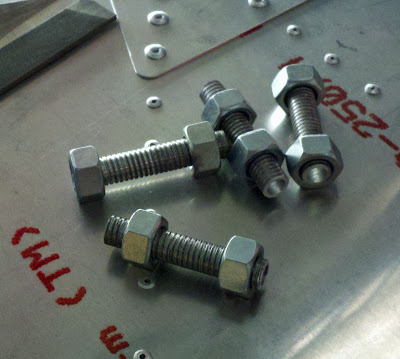 |
| Wing attach aluminum bushings and aluminum locknuts. |
The top rear bushing location is drilled out first. This hole MUST LINE UP WITH THE Y STRUT MAIN DRILL HOLE. DRILL OUT JUST THE TOP SIDE. DO NOT DRILL THROUGH THE SQUARE TUBE BOTTOM. DO NOT DRILL THROUGH THE BOTTOM OF THE WING SPAR. Insert a pin to hold location. Repeat for other wing.
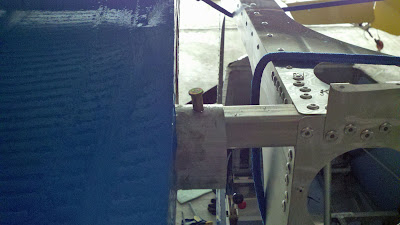 |
| The bottom is not yet drilled out, that's why this pin looks sloppy. |
After setting wing alignment, drill out the front spar top side as well and pin. Repeat for other wing.
 |
| Front spar also drilled out and pinned. |
All spars are now pinned. It is now easy to set the dihedral, as the wings will move up and down. As soon as the dihedral is set, drill out all four locations and pin completely. The wing is now rigidly in place, and if you drop the tip supports, you will destroy your cabin and/or your wing. Don't drop the tip supports.
Pull each pin out one at a time, drill out to the OD of the bushing, and install the bushings and lock nuts, along with locktight. You will then need to file each bushing on the top and bottom to ensure a perfect fit. You will also need to drill out each bushing to accept the pin or bolt.
 |
| Bushing installed. |
The wing may need to have its doubler installed. After installation of doubler, relieve back of rear spar fitting with a grinder or Dremel to allow wing folding.
 |
| Spar bushing installed and spar relieved to allow folding. |
CAREFULLY TEST WING FOLDING! There is possible interference at the Y strut attachment fitting. Relieve as necessary.
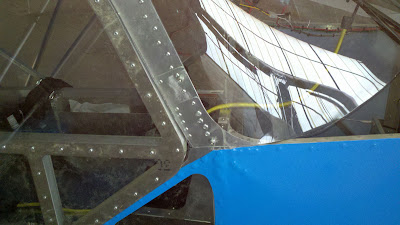
G. Attach the top cabin windshield ribs.
After painting, clamp each rib to the wing. This guarantees a perfect fit. Then fabricate the four attachment brackets, using the precut parts and angle aluminum. You will need to cut the angle aluminum to lengths which provide the best fit for your airplane. Rivet together; screw into wood ribs at top and bottom of bracket.
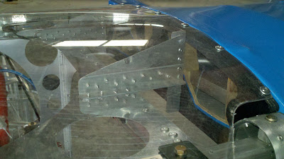 |
| Windshield attachment brackets. |
H. Attach the windshield.
Clamp the windshield to the X brace, fold to each side and clamp. Fold over windshield ribs and work screws backwards to rear.
Use nutserts on each side of windshield to allow easy removal of windshield.
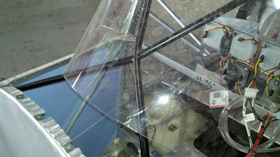 |
| Tight fit at lower front of windshield. |
 |
| Nutserts on sides. |
 |
| Another view of side of windshield. |
Your cabin assembly is done. In fact, your airplane is nearly done.