Tuesday, January 1, 2013

Belite Aluminum Ultralight Aircraft Cabin Construction, #7

Please note: James' blog has moved to a Wordpress site. To access it, please visit http://jameswiebe.wordpress.com/. All posts have been transferred to the new site, and all new posts will only be accessible via Wordpress. Thank you for your interest!


In our continuing series of aircraft construction articles, it's time for a photo review of the cabin assembly prior to covering.

Front Diagonal Support / Star Gusset area
Front view of cabin assembly.
View of Floor Pans, front assembly near firewall, first cross box.
Another view of floor pans and first cross box.
View of internal cabin assembly.  Baggage compartments on left side of photo.  Pivot location has been drilled and nylon 3/8" bushing is clearly (but barely) visible.
Lucky focuses on food.  Windshield support.
Cabin assembly from side.
Top gussets.
Nose of cabin assembly.
Top of cabin assembly.
Chance checks the weight of entire cabin assembly:  22.4 pounds
It is now time to cover the cabin assembly with dacron fabric.  Construction of the interior details of the cabin continues after you've covered the cabin assembly.

Belite Aluminum Ultralight Aircraft Cabin Construction, #6

Please note: James' blog has moved to a Wordpress site. To access it, please visit http://jameswiebe.wordpress.com/. All posts have been transferred to the new site, and all new posts will only be accessible via Wordpress. Thank you for your interest!


#6 in the series.

We will start by attaching the rear fuselage attachment gussets.  There are six:  two on each side, and two on the bottom.  The top side gussets, the bottom side gussets, and the bottom gussets are each unique.  They may vary slightly from these photos in appearance, due to fit and lightening improvements.  Fit, cleco, and rivet them in place, as shown in the following photos:

Bottom Side Gusset and Bottom Gusset, clecoed in place
Bottom Side Gusset, riveted in place
Top and Botom Side Gussets, riveted in place
Bottom Gusset, clecoed in place.
Rivet all six gussets in place.

Now we will work on attaching the 'sun roof skin' to the top of the cabin.

The front vertical pieces are marked and cut off with a dremel tool.
After cutting off the vertical angle aluminum supports, we can add in the two cross tube supports, which were are cut from 1" 6061T6 .063 square tubing.

6061T6 1 x 1 x .063 cross bars.  Cut to length shown.

We will also add in the 1" thinwall tubing, which runs along the top of top door skin, and is shown clecoed in and clamped in place in the following photo.   They are simply cut to fit.

All top cabin tubing shown
Top skin clecoed in place.
Another view of top skin clecoed in place.
Small inside gussets for top of cabin.
Riveting the top sunroof skin in place.
Closeup of corner of top skin.
You'll need to make a bend in the windshield support.

Windshield support with bend.
Windshield support clecoed in.
Windshield support riveted in.
Now it's time to cleco in the remaining baggage compartment dividers.

Pay attention:  the tabs may be bent either way, but only one way is correct.  Study the parts, your assembly to date, and all of the photos to ensure that you do it correctly.  The tabs are easily bent in any brake or even with a bench vise.  There are also hand tools which make them easy.

Baggage compartment divider.

Baggage compartment dividers in place.
Note that the bottom skin is not entirely pre-drilled.  This allows you to fit the best alignment on your baggage divider skins and under the front floor pan (which may require you to drill out a few rivets to fit under).

Bottom skin, ready to install.

 Bottom skin clecoed in place, fit under floor pan and under landing gear gusset.

Bottom skin partially riveted in place.
Rear Landing Gear gussets clecoed in place.
Fabric trim plate for bottom landing gear cross attach post.
Fabric trim plate riveted in place.
Front Diagonal Support gusset, bent and riveted in place.
Front Diagonal Support gusset, riveted in place.
Doublers at engine mount area
Doublers at engine mount area, riveted in place.

Top of cabin, ready to accept gusset.
Bent gusset.
Gusset riveted in place.  One of these rivets will be drilled out.
 One of the rivets will be drilled out in order to accept the "X" steel cross brace.

NEXT:  PHOTO REVIEW OF THE CABIN ASSEMBLY, PRIOR TO COVERING.

Belite Aluminum Ultralight Aircraft Cabin Construction, #5

Please note: James' blog has moved to a Wordpress site. To access it, please visit http://jameswiebe.wordpress.com/. All posts have been transferred to the new site, and all new posts will only be accessible via Wordpress. Thank you for your interest!


This post is #5 in a series of articles on how to assemble a Belite Ultralight Aircraft cabin using aluminum.

Post #4 in this series is HERE.
Post #3 in this series is HERE.
Post #2 in this series is HERE.
Post #1 in this series is HERE.

Let's jump right in...  It's looking more and more like a real airplane cabin all the time.

After deburring the top rear skin, clamp it in place:

Clamp the top rear skin in place.

Another view of clamped top rear skin.
Then proceed to clecos and riveting the skin in place.

Rear skin attached with rivets.

Rear skin fully attached with rivets.
If you haven't already, install remainder of rivets along each top side of cabin.  Please note and install extra rivets as shown in photo below.

Side rivets with extra rivets.
Now it's time to add the top side door skins.  Note how they UNDERLAP the star joint on each side.  Also note the windshield attachment piece in the following photo, it will be used a little later in the process.

Side skin and windshield attach piece.

Lucky poses.

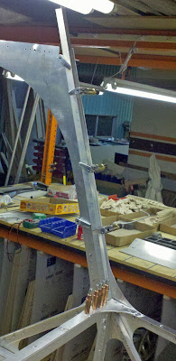
Front of side skin, with star joint underlapping clearly visible.

Alignment of side skin, viewed from front.

Rear view.  If all is done perfectly, the rear  corner has a nice sharp corner.

Another view of side skin.

Star joint area.

Yet another view.
It's finally time to fully rivet the star joint.

Finally time to fully rivet the Star Joint!

Done for this afternoon...  more soon.