Monday, December 17, 2012

Wild Mustang Horses in Kansas Flint Hills

Please note: James' blog has moved to a Wordpress site. To access it, please visit http://jameswiebe.wordpress.com/. All posts have been transferred to the new site, and all new posts will only be accessible via Wordpress. Thank you for your interest!


Quickly stated:

The shop gang installed the removable fairing on the back of the UltraCub, which made it look like a baby cub.  I was eager to fly it.

I flew the UltraCub from home base out to the Flint Hills (which are east of Wichita), where I took high res pictures of Wild Mustang horses, then returned home.  It was a 90 minute flight; and I used 2.5 gallons gasoline.  I returned with 90+ minutes fuel reserve at home base (slightly more than half tank remaining).  Fuel consumption:  1.67 gallons per hour.  Estimated fuel economy:  about 34 mpg.

Gentle Readers, the horse pictures are eye-popping, and you have to go to our belite flickr account to see them all.

Here's the link to the Wild Mustang horse photos on Flickr.  I have a couple of selected photos from the flight below.  The remainder of the wild horse photos (and there awesome photos of the horses) are on flickr.


Flint Hills, photo taken from Belite UltraCub ultralight airplane.

Wild Mustang Horses, photo taken from Belite ultralight airplane
Also note that that the four stroke UltraCub is now flying with the removable tail fairing attached:

Belite UltraCub ultralight airplane with four stroke engine
Walking the UltraCub 4 stroke ultralight airplane back to the hangar.

I used to do this flight in my Flight Design CTLS; it is absolutely a gift from God to be able to do it in the Belite.  I'm back to cruising around.  I'm planning cross countries to Oshkosh and Idaho.

Total time in the Burgundy UltraCub to date:  5.4 hours.

Here's the map of this adventure:

Wild Mustang Flight to the flint hills and back.

Flight speeds outbound to the flint hills averaged 65mph; return flight averaged 45mph.  Average groundspeed:  about 55mph.  You can see the variance on the position spacing above.  Cruise RPM varied from 2500 to 2700 rpm.


Sunday, December 16, 2012

Ultralight Cross Country?

Please note: James' blog has moved to a Wordpress site. To access it, please visit http://jameswiebe.wordpress.com/. All posts have been transferred to the new site, and all new posts will only be accessible via Wordpress. Thank you for your interest!


Personal note:  Thank you, Larry, for reading my blog. I did take that flight this afternoon, as I suggested I would.

Readers:  Please allow this post to wonder and wander around a bit, just as I did on a cross country flight in the burgundy plane.  Details on that flight are later in this post.

After I got to the airport shop this afternoon, I set to work on our production prototype of our new aluminum cab, which, when combined with a fuel efficient four stroke engine, produces the best ultralight aircraft on the planet.

There. I said it.  A boast:  "The Best Ultralight Aircraft in the United States".

There are seven reasons why this is so:

Engine Selection:  4 stroke aircraft engine with reliable operation and low fuel consumption
Airframe:  Aluminum; easy to build, lightweight
Utility:  Great short field performance; off - airport ruggedness
Flight Characteristics:  When trimmed, flies hands off; turns easily.
Extras:  Our carbon fiber expertise allows more strength, even lighter airframes and more options.
Covering:  Our Oracal process is producing the most beautiful airplanes, with less cost and less time than all other traditional aircraft coverings.
Cross Country:  I'll get to this last.  I had a great time flying away from the airport, then returning as sunset was imminent.

1.  Our engine selection.

We picked a 4 stroke engine built by Hummel Engines, and as their website states, this is "reliable four stroke power", and has been in use for years in various aircraft.  Our engine was ordered with all new parts, including aluminum Nicom cylinders.  We also ordered the largest bore and stroke that Hummel offered, and it has quickly proven to be a perfect choice for Belite.

Although this engine is rated at 45HP, we are using it in a derated manner, by limiting RPM to about 3150 RPM.  This gives us around 38HP at full throttle, which appears to be adequate to produce the maximum cruise speed legally allowed under US ultralight aircraft regulations.

This engine weighs 88 pounds, including carburetor, exhaust pipes, and dual ignition.

Christian Stratton had been working hard on fitting our Burgundy plane with a new firewall.  We'd been challenged to accomodate the sharp looking opposed cylinder engine in the Belite, and to eliminate Center of Gravity (CG) issues, the engine had been placed in a manner such that the magneto was poking into the cabin.  The new firewall fit beautifully; here's a photo of the revised engine installation and firewall.

4 Stroke engine on Belite Ultralight Airplane
And we provide some great two stroke options as well; nothing beats a Hirth F23 for raw stump pulling power.

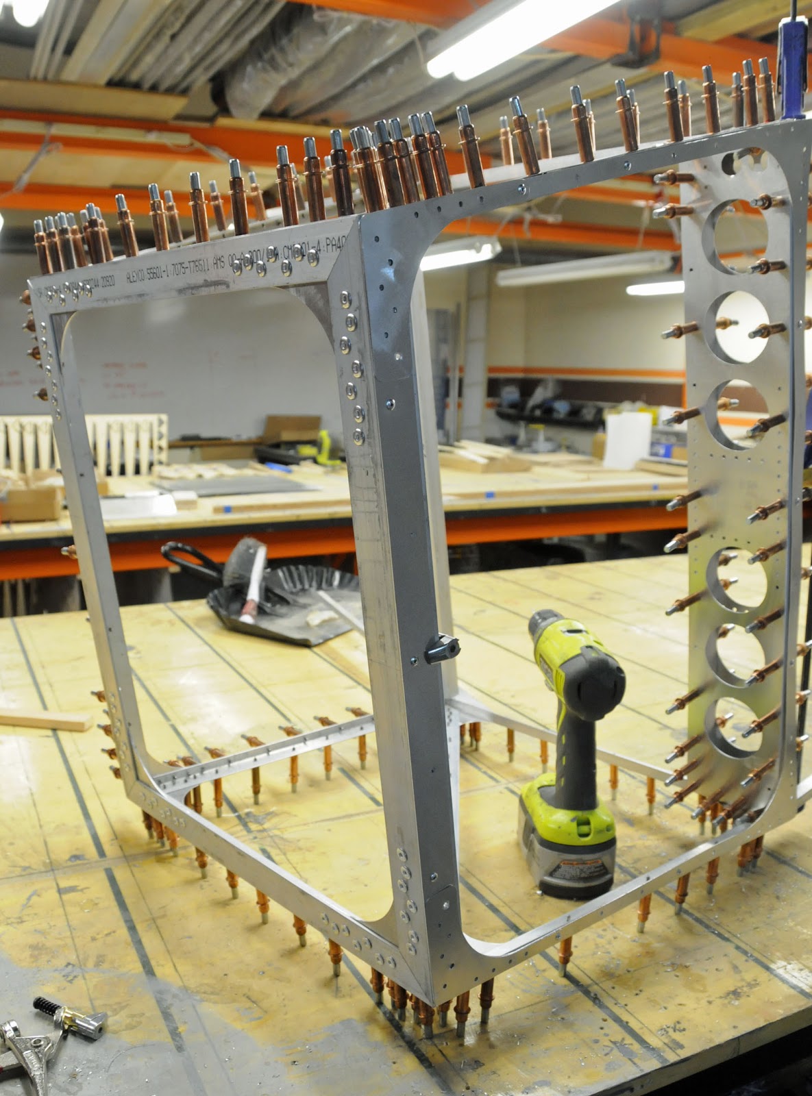
2.  Our aluminum airframe.

The fit and engineering quality on our aluminum cabin is just amazing.  Weighing in at about 22 1/2 pounds, this cabin sets a new benchmark for ultralight aircraft.  Pictured below is a cabin being prepared for a customer here in the state of Kansas:

Aluminum cabin assembly for Belite ultralight airplane, with Oracal covering

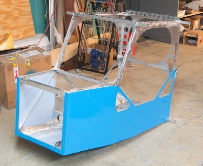
Let's take one peek inside this cabin, and look at the box construction along with the fit of everything.  The in flight storage compartments are on the lower left side:

Aluminum cabin for Belite ultralight airplane

3.  Belite has utility on and off airport.

When equipped with spring gear and appropriate tires, I've had no end of fun landing Belites in the neighboring uphill hayfield.  Great fun!  Caution -- good results require great skill.

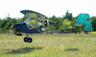
Hayfield landing in Belite Ultralight Aircraft
I did a fun post on this topic.  Read the Hayfield Post Here.

4.  Flight Characteristics.

The new UltraCub is flying by stick control only (see the video demonstrating this here.)  Alternatively, on my flight earlier today, I kept my hands off the stick and bumped the plane around using rudder pedals.  Take your pick.

5.  Extras.

I've enjoyed engineering some other options into the Belite.  Our carbon fiber spars are stronger and a great choice for customers who want less weight and more wing strength.  I'm working on some more options for the future; here's an example of a prototype Stabilator rib.

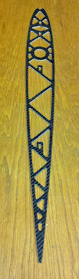
prototype Carbon Fiber rib for stabilator on Belite Ultralight Aircraft.
The pictured rib weighs about 2.1 ounces.

There's lots of other extras, but I won't belabor the point.  Read more about our airplanes on this blog or on our Belite website.

6.  Our covering process.

We're using Oracal, a vinyl covering which looks spectacular and easy to apply.  We've been using it for a couple of years.  Other automotive, aircraft, RV, motorcycle manufacturers use similar products for applying graphics onto pre-painted surfaces.  We take it a step further, and cover the entire airplane with it.

7.  Cross Country?

I wonder what the possibilities are.  Based on initial fuel burn analysis, fuel burn with the 4 stroke engine is running around 1.7 gph at low cruise.  I've got to get that number nailed down, along with 'cruise' speed at various RPM's and fuel flows.  Assuming fuel flow of 1.7gph with a 50mph speed, we've got a range of 145SM miles to dry tanks.  Combined with neutral or tail winds, there is a pretty good opportunity to go a long distance, and beat land transportation in the process.

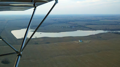
Earlier today, I took off in the burgundy Belite UltraCub and headed north, into a headwind.  I decided to fly  30 minutes northbound, then turn around and head home.

Here's some photos I took along the way:

Cross country in a Belite Ultalight Airplane

View of small town (Furley, KS) on a cold December day

Watershed ponds shrinking in size, due to drought

Farm house and wheat field

Actually, this pond is doing OK.

Harvey County east lake, photo taken from Belite Ultracub with 4 stroke engine
I turned around and headed home.  It took 30 minutes at low cruise, into the headwind, to get there.  I upped the power and climbed into a nice tailwind heading home, which took 20 minutes.

I'm starting to think, again, of flying to Oshkosh next summer in a Belite Ultracub.  We'll see.

Total Time in the burgundy plane to date:  3.9 hours.

The following day, I took the Belite UltraCub out to the flint hills to take hi-res photos of wild mustang horses.  You can read about that HERE (click).


Saturday, December 15, 2012

Belite Aluminum Ultralight Aircraft Cabin Construction, #2

Please note: James' blog has moved to a Wordpress site. To access it, please visit http://jameswiebe.wordpress.com/. All posts have been transferred to the new site, and all new posts will only be accessible via Wordpress. Thank you for your interest!


This is the second section on building an aluminum cabin for a Belite ultralight aircraft.  We're well on our way to finishing an awesome cabin for a single place airplane.  When completed, this cabin will weigh about 22 1/2 pounds and will match the look of other experimental (and factory) airplanes costing much, much more.

The first section in this series is HERE.

All caveats and warnings from that section apply in this section as well.  Remember, under federal law, you are personally responsible for ensuring the safety of your ultralight aircraft every time you fly, so do a good job.

Start by cutting two lengths of structural aluminum.  Each piece looks like this:

Short length of angle aluminum.
And each piece fits on the left or right side of the front cabin cross box assembly, as seen in this photo:

Short length drilled and clecoed in place.
Note that a long clamp is being used to pull both sides of the cabin snugly together.

Front Cabin Cross Box with both skins clecoed in.
Now it's time to clamp in the bottom gusset.

Bottom gusset clamped in place.
Bottom Gusset gets a few rivets.  (Cabin is on side.)
Be judicious in the use of rivets on the bottom gusset.  In the above photo, there are a couple of rivets placed (mistakenly) which were immediately drilled out in order to allow the floor pans to slip into place.  However, the objective is to get all of the bottom rivets in, so that the cabin assembly can set on the bottom and moved around without dragging the bottom tips of all of the clecos.

Floor pans as received and after bends.
Your pair of floor pans need to be bent into shape, as shown above.  The pre-cut relief slots make this easy to line up and do. Also, if you have shorter legs, you may wish to drill out and reset the position of the rudder pedal and brake bearing holes.  In general, the position of the holes should work well as set for pilots between 5' 8" and 6' 4" in height.  Shorter pilots may use a back cushion on their back seat, and anyone with truly short legs should consider resetting the pedal location.

Floor pans clecoed in place.
Make sure your floor pans are put in square to the cabin assembly, as one end does not have matching drill holes.  Also note that doubler gussets have been clecoed in on each forward corner.

Bottom front section riveting.
Above is a photo that shows what it looks like after riveting the bottom front section.  Note that many holes have been drilled out for 3/16" rivets.  Also note:  look through the remainder of the assembly instructions, as a metal sheet will be slipped under one side of the floor pan.  The metal sheet is the bottom of the mid cabin storage cabins, and its front edge has to slip under one of the floor pans and also under one of the front landing gear gussets.

Front Landing Gear Gusset.
To be continued.

Monday, December 10, 2012

Belite Aluminum Ultralight Aircraft Cabin Construction, #1

Please note: James' blog has moved to a Wordpress site. To access it, please visit http://jameswiebe.wordpress.com/. All posts have been transferred to the new site, and all new posts will only be accessible via Wordpress. Thank you for your interest!


THIS IS PART 1 IN THE CABIN ASSEMBLY SERIES.

Part 2 may be found HERE (click).
Part 3 may be found HERE (click).

Let's dig into building an aluminum cabin for a Belite Ultralight Airplane.

Sometimes, it's good to have a vision of where we are trying to get, and in our case, it is represented by the following photo:

Belite Aluminum Cabin for ultralight airplane


Here's the ground rules:

a. 99.97% of all holes are pre-drilled.  There are a few you have to drill, for reasons which are usually obvious.  You'll have to drill into the matching longerons and tubings, and this is very easy because it matches to the holes in the gussets.
b.  Every piece of aluminum gusset is pre-cut and pre-drilled on our CNC machinery.  The accuracy is amazing.
c.  You are responsible for cutting and fitting aluminum longerons (all metal square tubing and angle material) to length.  This is easily done on a bandsaw or a tablesaw, but if you use a tablesaw, you must use a carbide blade.  Wear eye protection.
d.  Make sure you clean and deburr all components.  I will never bring this up again in this document, but you will see plenty of evidence of deburring in the photos.
e.  A few clecos go a long ways.  I also like to use cleco clamps.  We buy them for $4.95 / dozen in Wichita, and you can do the entire airplane with a hundred or so.  Two hundred would be a little better.
f.  We include some 1/8" rivets in the kit to get you going.  We don't include 3/16" rivets.  Our rivets are aluminum / steel commercial quality rivets.  You may wish to upgrade to aircraft grade rivets.  In certain locations, you may wish to buck solid rivets.  Always make sure you use the appropriate length of rivet.
g.  All holes in the pre-drilled gussets are 1/8" in diameter, but many of the holes will be drilled out for use with 3/16" rivets.  Examine the construction photos for advice.
h.  Don't get ahead of the pictures.  Don't drill out if it's not drilled out in the photo; don't rivet if it's not riveted in the photos.   Having said this, there are still a few spots where you'll have to drill out rivets after they've been pulled.
i.  Make sure you get everything square.  There are not many places to screw up, but a good example is the second step, where the front left and right parts are clamped on.  Make sure they are exactly matched to the front of the firewall frame.  Check squareness.  Build on a dead flat table.  Use sharp drills.  Go slowly.
j.  Read and understand all of these instructions before doing anything.


1.  Firewall Frame.  Cut the Firewall Frame from 7075T6 angle aluminum, with 45degree mitred corners.  Temporarily Cleco with corner gussets (also 7075T6 aluminum). Drill out and assemble using 3/16 rivets.

Firewall Frame for Belite Ultralight Aircraft

2.  Clamp Front Left and Right Master Gusset.
Clamp on Front Left and Right Master Gusset. 

3.  Clamp on Left and Right Longerons.  These are approximate 60" in length.  They are 2024T3 aluminum, with dimensions of 0.875 x 0.500 x 0.063".  Other than the firewall, this is the only angle aluminum used in our cabin, and we will call it "structural angle" hereafter.

Clamp on Left and Right Longerons.
They are butt jointed on the inside, as shown in the photo below.
Butt joint of Longeron.
3.  Cut two pieces of structural angle to 16.25" in length.  Clamp and cleco in place.

Two pieces of structural aluminum, cut to 16.25" in length
16.25" structural angle clamped and clecoed in place.
4.  Clamp on Front Top and Bottom Master Gussets; also vertical longerons.

Front Top and Bottom Master Gussets.  Bottom is slightly longer as seen in above photo.
The Vertical Longerons are 40" in length.  They are cut from structural aluminum.
Vertical Longerons are 40" in length.
Front Top Master Gusset clamped in place.  Your gusset may be pre-notched.
Vertical Longeron clamped in place.
Butt joint on bottom of Vertical Longeron.
Vertical Longeron clamped in place.
Use a Sharpie and make a mark on each Vertical Longeron, through the hole in the photo below:

Marking dot thru hole onto Vertical Longeron.
You must make a V cut in each Vertical Longeron at the marked location.  The V cut must be larger than necessary, as it is impossible to unbend and rebend it, because the metal will fail in fatigue in two bends.

(Multiple overlapping gussets carry all flight loads at this spot, but its nice to have the Vertical Longeron holding together).
Make a V cut in each Vertical Longeron at marked location.
Then reclamp the Vertical Longerons in place.

5.  Cut and fit Diagonal Longerons from Structural Angle.

You need to cut and fit two Diagonal Longerons from Structural Angle.
Diagonal Longerons cut from Structural Angle.
Diagonal Longerons being fitted to Front Left and Right Master Gussets.
Butt joint on Diagonal Longerons.
6.  Cleco in doubler gussets on Front Top Master Gusset.

The doubler gusset is inserted into the cleco assembly at each front top corner.

Doubler Gusset added to Front Top Master Gusset.
7.  Clamp on Front Bottom Master Gusset.

Front Bottom Master Gusset being clamped in place.
Marking position of notch in Left and Right Longerons.
You'll need to make a notch in the Left and Right Longerons at the marked spot, which is displaced 1/8" from the edge of the Vertical Longeron.
Notch made in Left and RIght Longerons, displaced 1/8" from alignment mark.
After the notch is made on each longeron, it's an easy matter to pull in the two longerons. using clamps or weights:
Left and Right Longerons pulled in
A piece of 3/4" thin wall square tubing is cut to 23 3/4"+.  After trimming to the correct length, it is clamped to the Front Top Master Gusset.

Clamping in square tubing
8.  Build up the First Cross Box.

It's built from two gussets (First Cross Box Front and Rear), along with dual matching lengths of 3/4" thinwall aluminum tubing.

First Cross Box being built.
First Cross Box, view from front.
That ends our first installment on how to build a Belite Aluminum Cabin.  We'll pick it up again in a few days.