Here's some photos showing some of the ways our fuselage design has mutated from 4130 steel. I've also made some comments on strength.
The front of the fuselage is made from 6061T6 aluminum, and is welded. The rear of the fuselage is made from 2024T3511 aluminum, and is riveted.
The hallmarks of this design is that it is very light, very strong, and easy to assemble. Let's look at some pictures. The first picture shows that the primary vertical members are 1.0" aluminum square tubing, with .063" walls. Although the temper is 6061T6, the welding is assumed to reduce the strength. This particular tubing doesn't have the heavy loads. However, it is also a primary safety mechanism to enclose the pilot in the event of an accident, so we still want it to be strong. Assuming 0 temper, the strength of this material is about 4,500 pounds per tube cross section.
 |
| 1" square tubing used in Belite ultralight aircraft | | |
|
|
The front section of the fuselage is where the engine mounts attach. We've reinforced this section with 4" gussets. Here is a gusset at the top of the front fuselage:
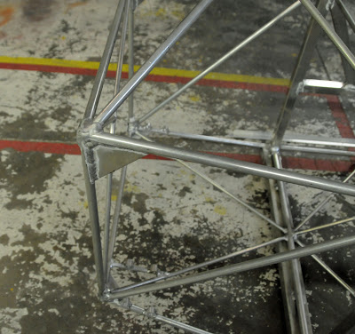 |
| Gusset reinforcement |
|
|
And here is a gusset on the bottom of the front fuselage:
 |
| Gusset reinforcement is on bottom of fuselage | | |
|
|
Now let's look at the front spar crossover. It is constructed of aluminum tubing (about .080 wall) with reinforcements in both axis. As a result, it has a critical length of about 12 times its diameter, which means that the effects of "Euler's Buckling" have been reduced or eliminated. At normal loading, this spar crossover has about 650 pounds of force pushing through it. At a 4G load, it would have around 2600 pounds of force. Assuming 6061T0 temper (welded), the cross section strength of this material is about 4000 pounds.
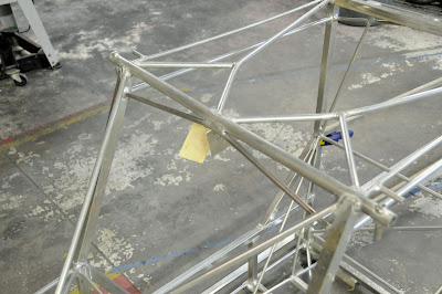 |
| Front Spar Crossover with reinforcements. |
Now let's take a look at the rear spar crossover. We've reinforced it with some 1" square material. The failure strength is substantially stronger than the front spar.
 |
| Rear spar crossover with reinforcement | | | |
|
|
|
Here's another view of the rear spar crossover:
The above photo shows the bracing. The braces help prevent the cockpit from torsionally twisting.
 |
| rear spar crossover with bracing shown |
|
The pilot's seat also gets some strengthing:
 |
| 0.5 x 1.0 aluminum tubing added to pilots seat |
Tricycle gear versions of our planes get extra cross channels on the bottom, along with more bracing in the side cabin area:
 |
| Tricycle gear airplanes get even more cross channels | |
|
|
And now let's show how the rear fuselage is added on. We start with four longerons built from 2024 aluminum, with an angle size of 0.875 x 0.5 x 0.063 inches. We then add some bulkheads, a vertical stabilizer, and some rivets. We also use gusset plates. Since there is no welding in the rear of the fuselage, the 2024 is an excellent choice. (You can't weld it, but good golly goodness is it strong.) Tensile strength of the longerons is off the charts: each longeron could lift nearly 5900 pounds. In a few more days, I'll have some photos of the completed rear fuselage.
 |
| Rear fuselage of Belite's aluminum airplane |
|
|
|
 |
| rear view of the rear fuselage of Belite's ultralight aircraft |
 |
| front view of the fuselage, it's all coming together |