
Mandatory Service Bulletin #4
Supercedes MSB #1
The purpose of this MSB is improve the strength of the main gear head bulkhead, replacing the original 5.25" x 0.25" machined part with a solid, larger part.
The desired outcome is a bulkhead which will enlarge the footprint spread of the landing gear brackets, which reduces torque caused by landing stresses, and also allows for a greater distance for bolt holes to the edge of the bulkhead, reducing or eliminating the problem of cracking.
Also included is a much larger angle piece for each side, allowing for better transfer of landing gear loads into the side 1/8" aluminum pieces.
This MSB also contains directives for potting bolt locations within honeycomb, substantially improving strength.
This MSB also contains directives for bonding metal surfaces such as angle and flat sheet, which will substantially improve the strength of connected components and provide improved longevity for the airframe over time and service cycles.
This MSB allows future use of the bulkhead for hard points such as floats, shock absorbers, ski's, under fuselage storage container.
This MSB is required prior to installation of shock absorbers, which will be required for a possible future Gross Weight Increase to 1320 pounds.
Estimated time to install: 60 hours
Review and understand ALL INSTRUCTIONS prior to performing any work. As an example of one possible sequence error, potting of honeycomb for bolt installation is mandatory and must be performed prior to assembly. Without reviewing this material first, you may find it difficult to pot your honeycomb in sequence.
Supplied Materials:
1) this MSB manual, complete with large printed illustrations
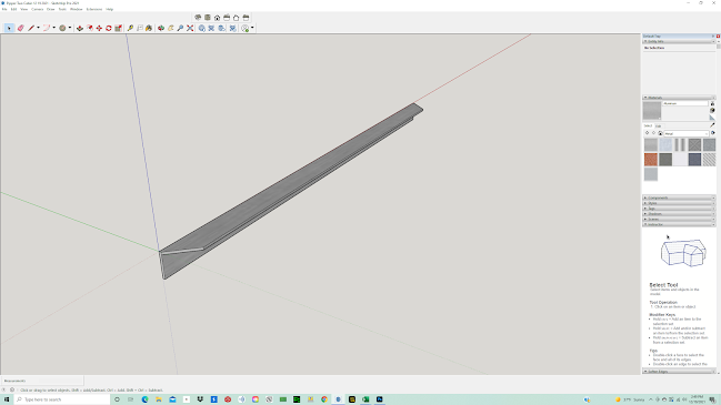
2) 41" x 6" x 0.25" 6061T6 aluminum bar, solid
3) 41" x 2" x 2" x 0.188" 6061T6 aluminum angle, cut with dogleg angles at each end
4) 6" x 3" x 2" x 0.188" 6061T6 aluminum angle, cut to shape and pre-drilled (advise if you do not want it drilled)
5) 2" x 2" x 24" x 0.040" 6061T6 aluminum angle, bent to shape and predrilled with rivet location holes
6) AN nuts, washers, bolt kit
7) 1" aluminum square tube, separately used to actuate flaps (not a part of this MSB, but missing from many kits).
Needed but not included:
1) scrap material: honeycomb aluminum
2) bonding adhesive, such as 3M 2216
3) rivets
4) 80 grit sandpaper
5) acetone
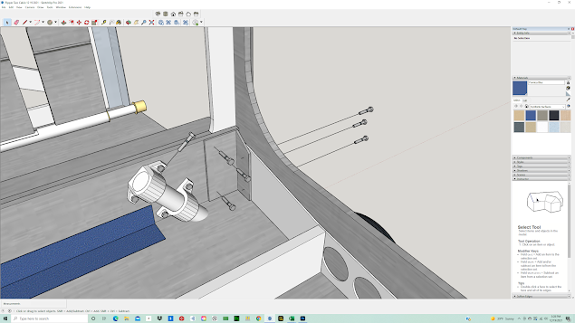
The original design is similar to the following CAD illustration, where the main gear bulkhead has lightening holes. Other details within this CAD illustration are not consistent with shipped kits.


No comments:
Post a Comment