Please note: James' blog has moved to a Wordpress site. To access it, please visit
http://jameswiebe.wordpress.com/. All posts have been transferred to the new site, and all new posts will only be accessible via Wordpress. Thank you for your interest!
This is series #8 in our Belite Aluminum Ultralight Aircraft Cabin Construction articles.
It's back to work on the aluminum cabin for a Belite ultralight airplane! We're going to be working on the internal details now.
BTW, your cabin should now be covered. You'll need to take care as the cabin is worked on, in order to not tear or scratch the dacron fabric. This is critical because you'll be slitting the fabric and mounting the landing gear center brace through the fabric.
We've taken the liberty of additionally covering our cabin with turquoise Oracal, which is our fantastic covering method.
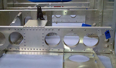
Our two tasks today are closely related: we'll mount the landing gear cross brace, and we'll build and mount the control stick mount box.
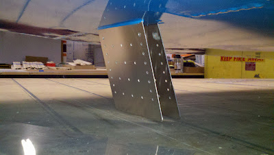
There are two landing gear cross brace plates. They look like this:
 |
| Landing Gear Cross Brace Plate for Belite Ultralight Aircraft. |
After bending each piece, and slitting the fabric on the bottom of the cabin, the pieces are inserted through the slits and riveted in place.
 |
| Landing Gear Cross Brace Plates inserted through slits in fabric |
 |
| Landing Gear Cross Brace Plate riveted in place |
Two short pieces (approximately 4 1/4") of 3/4" thin wall square tubing are cut in place and clamped, as shown in the photo below.
 |
| Landing Gear Cross Brace Plate with tubes clamped in place. |
 |
| Rivets in place on Landing Gear Cross Brace Plate |
 |
| another view of Landing Gear Cross Brace Plate |
Now collect the three pieces of metal which comprise the control stick support box.
 |
| Control Stick Support Box sides |
 |
| Control Stick Support Box top. |
 |
| Side with tabs bent. Use a brake, or a vise, or wide jaw pliers, or helpful friends. |
 |
| Top with bend |
 |
| Box with clecos. |
 |
| Box with rivets. |
 |
| Box clecoed to cross box. |
Note that in the following photo, the steel pivot arm has appeared. You'll want to check fit with it very thoroughly before riveting, as the instructions for its mounting follow! Also note that the attachment bolt is an AN4-7 with washers and a locknut.
 |
| Box riveted to cross box. |
So let's investigate what needs to be done to attach the steel pivot assembly.
 |
| Bearing for pivot assembly. |
 |
| Bearing bolted in place with two AN3 bolts. Do not overtorque! |
 |
| Closeup of AN3-17 bolts used to attach bearing. |
 |
| Test fit. |
The control stick pivot should rotate with complete freedom.
 |
| Another view of assembly, complete. |


2 comments:
Looking good. Couldn't you attach the LG tension members at the fuselage without the sheet metal drop down box? Your relatively deep cross member structure inside looks like it could easily handle the increased bending loads this would impose. Would this overload the main compression members of the LG? I would personally prefer slightly shorter gear if it would eliminate the extra box structure (I also hate extra frontal area in the prop blast). It's been fun and interesting watching you improve the design. Keep it up!
The placement of the drop box matches the original Kitfox Lite, more or less, and allows us to continue to offer interoperable gear, solid links, bungee links, and our state of the art spring gear. But your basic idea has no flaw, other than keeping compatible with history...
Post a Comment