Please note: James' blog has moved to a Wordpress site. To access it, please visit
http://jameswiebe.wordpress.com/. All posts have been transferred to the new site, and all new posts will only be accessible via Wordpress. Thank you for your interest!
Assembly of a rear truss structure aluminum fuselage
for a
Belite Ultralight Aircraft
It’s easy to assembly a rear fuselage for a Belite ultralight airplane!
1. PARTS INVENTORY
CHECK
Your kit should have the following items in it:
A)
Pre-riveted frames, constructed from 2024T3 aluminum,
7/8” x ½” x .063”.
B)
Longerons, with tabs already attached. Also constructed from 2024T3 aluminum.
C)
Rear post, with pre-welded rudder hinge point.
D)
Gussets. Gussets
are made from either .032 or .040 aluminum, 2024T3 or 6061T6.
E)
Truss pieces, constructed from 2024T3 aluminum.
F)
Rivets – commercial grade. If you are interested in using aircraft grade
rivets, we encourage you to purchase them directly from Aircraft Spruce, or the
supplier of your choice. We do not
supply them.
G)
Top skin aluminum, pre-routed.
Here is the pictures of the parts:
 |
| Section Frames, Six of them, A through F. |
The frames are ‘A’ through ‘F’ as shown on the
blueprings. Each is riveted
together. All are easy to identify by
comparison to the blueprints, with one exception: One of these frames has a dimension of 19 by
19 1/8”. Don’t confuse the vertical dimension
with the horizontal dimension on this one frame; look carefully at your
blueprints.
 |
| Longerons with gussets. |
The longerons come pre-riveted with gussets.
 |
| Truss sections. |
The truss sections are all
labeled as shown. You may also notice
color coding, which we do to help you sort out where the truss and frames rivet
together.
 |
| Rear post. |
The rear post is pre-welded for rudder attachment. DO NOT RIVET to the top of this post as it
has to receive the vertical stabilizer, rivets would obstruct inserting the
vertical stabilizer post.
 |
| Gussets. |
The gussets are obvious in use, especially after reviewing
all photos.
*PLEASE NOTE that we are now using small triangular gussets INSTEAD of the small wrap-around gusset
shown on the bottom right of this photo.*
 |
| Top skin, predrilled. |
The top skin is also drilled and ready to rivet in place.
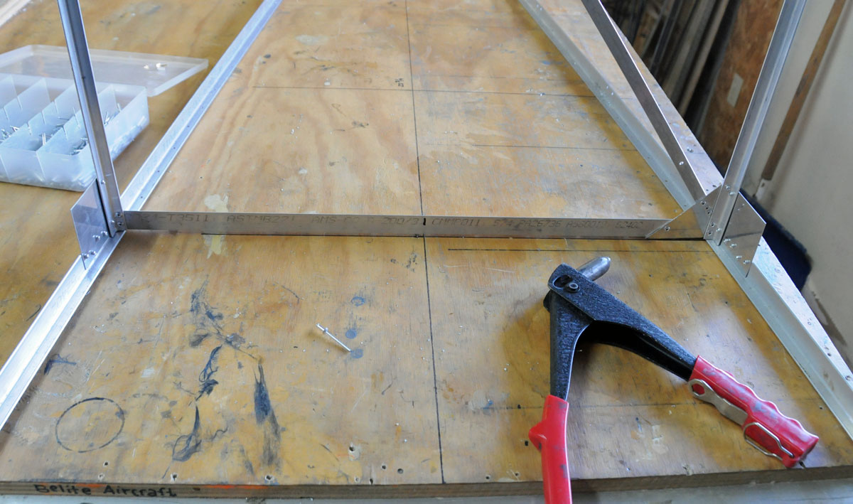
2. WORKBENCH AND
PROJECT PREPARATION.
We recommend that you prepare your absolutely flat workbench
with a centerline (denoting the center of the fuselage and positions for each
of the frames. You can see these lines
throughout our photos.
The fuselage is built upside down. The top longerons are placed on the
workbench; the frames are riveted in place; everything is placed absolutely
dead square to the workbench (90 degrees to the table top.) Use squares, clamps, and whatever else you
need to keep it all completely square.
Measure twice and drill once.
All holes should be de-burred. It is our experience that the 2024 aluminum
alloy makes very clean holes, with very little chipping or burrs on the edges
of the holes.
We supply commercial grade rivets with the fuselage. There is no place on the fuselage that requires
aircraft grade rivets. However, if you
encounter low quality commercial grade rivets, don’t hesitate to drill them out
and replace as appropriate. (As an
example, you can tell a bad rivet by a non-uniform pull force.)
The entire fuselage may be reassembled, prior to riveting,
using Clecos, which we do not supply.
Having the entire fuselage in its final form may provide you with a
great deal of certainty that you are doing it correctly, but this choice is up
to you. If you choose to use Clecos,
your fuselage project may look like this:
 |
| Clecos in use |
And here is another pictures of clecos:
 |
| More clecos in use |
Let’s get to work on putting this fuselage together.
3. FUSELAGE ASSEMBLY.
Lay the top longerons and small rear gusset plate on the
work bench. (Remember, this is upside
down.)
 |
| Top longerons. |
Now rivet the rear plate in place. (We recommend riveting this plate in place,
even if you are using Clecos.)
 |
| Rear plate and top longerons |
Place the “A” frame in place as shown in the photo,
below. Note that a cross brace has also
been placed on this A frame; make sure that the A frame is absolutely
square. The cross brace supports load
from the fuel tank, which eventually rests on the cross member of the A
frame. Use any aluminum for the cross
brace.
 |
| 'A' frame in place, along with cross brace |
 |
| Rivets at base of "A" frame |
Rivet the A frame in place.
In the photo above, you can see a typical rivet pattern in the A
frame. Our gussets are now cut on our
CNC shopbot and are much ‘prettier’ than shown above.
 |
| "A" frame centered on workbench and riveted in place |
Note how the center of the A frame has been centered onto
the workbench centerline. Both sides are
riveted in place.
 |
| Weight placed on top of "A" frame |
A weight has been placed on the A frame to keep it from
moving.
Now, place all frames in place and rivet.
Note that all frames are exactly where they need to be, and we use
weights to keep them in place. The
longerons are matched exactly with the beginning of our table (barely visible
in lower left corner):
 |
| A through F frames in place |
 |
| Rivet holds frame to longeron |
Each frame is held by a single rivet at this time. A second rivet will be drilled and placed,
later. The gap in the frame is expected,
as shown in the above photo. And although
you can’t see it in the above photo, the rear of each frame has been beveled so
that it will clear the interior of the longerons.
Additional longerons are then placed along the opposite side
of each frame.
 |
| Longerons on other side of fuselage |
 |
| Rivets in gussets |
The rivets are placed into the new longerons and frames as
well, as shown above. Everything needs
to be square and line up, as shown in the photo below.
 |
| Fuselage view down center top |
 |
| Fuselage view down inside |
 |
| Rear gusset |
The rear gusset is used to hold the longerons in place. Note that rivets have been used to keep the
longerons together, but the rivet pattern has not yet been filled out.
NOTE: Taildraggers
use FOUR of these plates (quadrupled thickness); tricycle gear aircraft use TWO of these plates (doubled thickness).
 |
| Rear post |
The rear post is also held in place temporarily with rivets.
 |
| Another view of rear post |
 |
| Small Wrap gusset |
NOTE: the gusset in
the above photo has now been replaced with two triangular gussets, one on each
side. It’s much easier to
fabricate.
 |
| Large wrap gusset |
The other end of the rear post will accept the vertical
stabilizer. It is notched into the
longerons, then held in place with a doubled wrap around gusset.
Figure 27 Rivets on wrap around gusset
Now it’s time to start adding truss sections, starting with
the rear gusset, then moving forward to other frames:
 |
| Rear post with truss added |
 |
| Another truss added |
All of the truss sections are added and riveted in place:
 |
| All trusses in place |
And one reinforcement is added, parallel to the rear post. It is in the photo below, immediately flush to
the rear post. Because the rear post may
not be riveted, this parallel structure provides compressive strength to the
rear assembly.
 |
| Rear post with parallel reinforcement. |
 |
| Typical gusset; two rivets per frame |
Each frame and gusset is riveted out. Note that each frame now has two rivets
connecting it to the longerons.
 |
| Big gusset on rear post |
You will also need to flip the fuselage over and add the top
skin. It is possible to place
without clecos, but go very slowly, line it up very carefully, and make sure
every frame and centerline is square.
 |
| Top skin in place. |
After riveting, it’s Done!
And ready to attach to the fuselage cabin.
The rear fuselage must be covered with fabric (after
assembly to cabin) in order to have adequate strength. Make sure you review final assembly
requirements prior to covering.