Please note: James' blog has moved to a Wordpress site. To access it, please visit
http://jameswiebe.wordpress.com/. All posts have been transferred to the new site, and all new posts will only be accessible via Wordpress. Thank you for your interest!
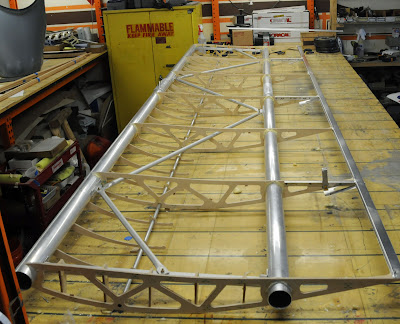
Back to my wood wing build update. It's another series of pictures, and we're picking up exactly where we left off a few days ago.
(My earlier post on this wood rib wing topic may be found
here).
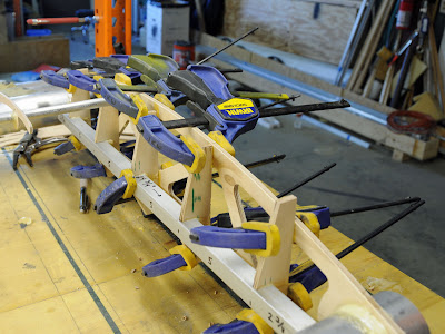 |
| Clamping on the anti warp anti crush tubing. |
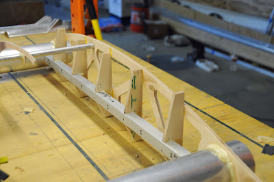 |
Clamps removed showing anti crush anti warp structure.
|
 |
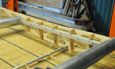
| Gluing 4 inch wood gussets, 1/4" thickness, to ribs. |
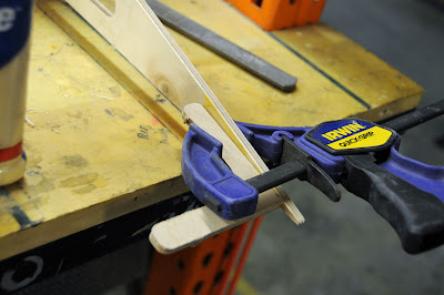 |
| Glue up for gussets, close up. |
 |
| Trailing edge riveted in place. |
 |
| Slot cut on some ribs to fit flaperon hard points. |
 |
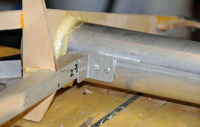
| Flaperon attachment right angle material, with spacing for 3/16" rivet holes shown. |
 |
| Flaperon attachment clamped in place, showing 1/4" overhang at rear of trailing edge. |
 |
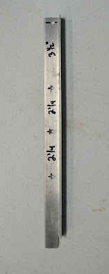
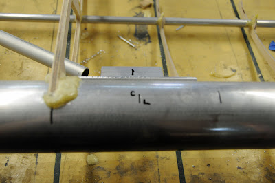
| Flaperon cable post, showing how it has to be cut and drilled. |
In the above photo, the post is backwards. This was fixed later in the assembly. Also, the mark barely visible on the top of the rib is 6" from the trailing edge.
 |
| Use 3/16" rivets and large backing washers. |
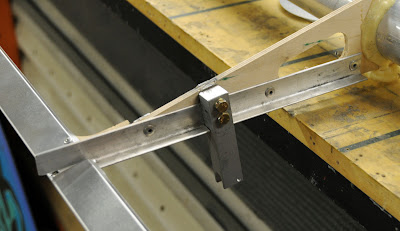 |
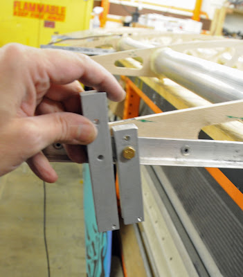
| Post bolted in place using AN3 bolts, cut down washers, spacers as necessary. This post is still backwards. |
 |
| Right angle with two 1/8" rivet holes each side. 3/4" x 3/4 x 3/4, or larger. |
 |
| Rivet four right angle braces in place. (Two at each end of rib; both end ribs.) |
 |
| Complete anti-crush anti-warp structure in place on end rib. |
Note that the wood 'riblets' have been trimmed. Consider using a deeper cut angle on the riblets than as shown. This will aid in covering the wing with fabric later on, so that the riblets don't interfere with fabric.
 |
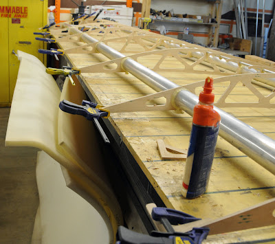
| Hardpoints for anti-sail tubes will be riveted on spars. Exact placement determined by tubing lengths. |
The length of the anti-sail tubes is 2', 4', 3', 3' 1", and 2'. For these tubes, we're using 3/4" thin wall aluminum tubing of a soft temper. The ends flatten easily in a vise.
 |
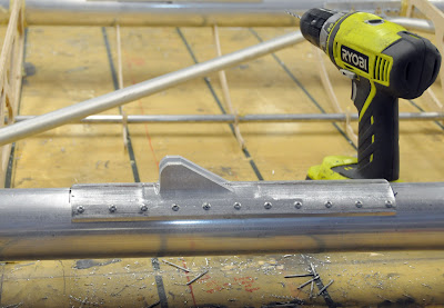
| Anti-sail hardpoint riveted in place. |
 |
| Anti-sail tubing layout. 2', 4', 3', 3'1", 2' lengths from near to far. |
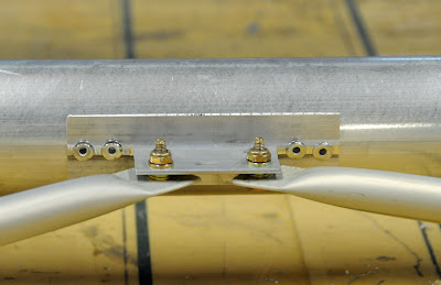 |
| Anti-sail hardpoint with AN3 bolts. Use appropriate washers to ensure clearance. |
 |
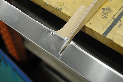
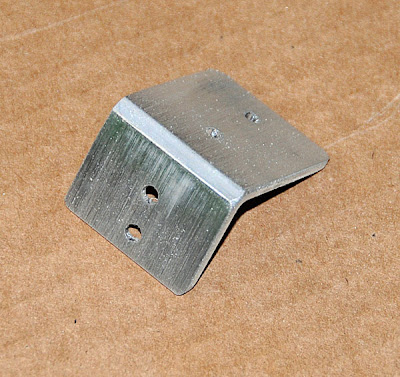
| Lift strut machined attachment, riveted in place. |
This is one step to check, recheck, and triple check the placement of each lift strut fitting. This is also one area that I insist on using aircraft quality rivets, with their higher shear strength.
 |
| Trim plates riveted in place. |
 |
| Another view of trim plates. Note spacing washers under plates/rivets to ensure straight / parallel trim plates. |
 |
| Pitot tube installation using 1/4" aluminum tubing and grommets. |
 |
| Routing of pitot tubing line. |
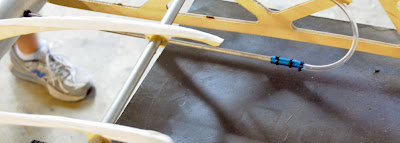 |
| Another view of pitot tubing attachment. Pitot tube may extend and retract. |
 |
| Trailing edge material butt joint. Sweet and simple. |
What's missing from this post?
a) Never did show the installation of the jury strut fittings. I'll add that.
b) Didn't show the wooden structure being painted with spar lacquer.
c) Didn't show the fabric covering.


4 comments:
The attaching of the pitot tube is the most tricky among the steps as it may extend or retract. Whew! I’ll be waiting for the photos of the installation of the jury strut fittings!
I am learning more. Thanks James, you are a good man.
It looks like the strut attachment is held on by the rivet heads, rather than by loading the rivets in shear. I would think that the strut attach plates would mount on the side of the wing spar and not the bottom.
Just curious, but what is the size of the main spars? Diameter and wall thickness?
Post a Comment