 |
| A completed wing. It weighs 20 pounds. |
Last Updated December 13, 2010
I have finished my online edits to this revised wing assembly manual. Further edits are contained within the latest version of the builder's manual, included with each kit. No further online edits are planned at this time.
Updated December 7, 2010
Updated December 4, 2010
Updated December 2, 2010
Updated November 30, 2010
Updated November 28, 2010
0. INTRODUCTION
When you are done with these wings, you will have state of the art ultralight aircraft wings utilizing carbon fiber and aluminum. They will work well with our FAR Part 103 Belite Aircraft! The weight of the left wing (without flaperon or covering, but including the flaperon control cable and pitot tube/tubing) is slightly less than 20 pounds (9.1KG) when complete. The weight of the right wing is 19 pounds (8.6KG).
Construction is straightforward, requiring only the ability to accurately place and glue parts together, with minimal riveting and absolutely no welding.
If you are building with aluminum spars (instead of carbon fiber) and wooden ribs (instead of aluminum ribs), you will only need to make slight modifications to the build instructions to complete your wings.
1. VERIFY CONTENTS, YOUR WORKSPACE, AND YOUR TOOLS.
First of all, check your materials. For each wing, you should have the following:
a) QTY 2 Carbon Fiber spars, with pre-attached CNC Machined lift strut hard points
b) QTY 5 Aluminum ribs
c) QTY 2 Birch Ply ribs, CNC machined from 1/2 inch Birch plywood (for root and tip caps)
d) Aluminum Tubing - 6 inch (length) used for doubler for spar roots
e) Aluminum Tubing - 1.5 inch (length) tripler used for spar roots
f) Aluminum Tubing - 0.5 inch OD x 0.035 wall thickness, 6061T6, used for false rib spar and sail/anti sail braces. A total of 5 tube lengths of varying lengths are needed for sail/anti-sail tubes. 12' is needed for false rib spar.
g) Aluminum Tubing - 0.625 OD square x 0.035 wall thickness used for rib stiffeners and sail/anti-sail hard points
h) Aluminum Sheet - 0.025 thickness used for front spar strap, you will cut to 10" by 0.5" straps.
i) pitot tube - 1/4 inch aluminum tubing, prebent to shape.
j) plastic tubing for pitot tube
k) QTY 2 machined jury strut attachment fittings
l) preformed trailing edge aluminum, 12' per wing
m) LEFT and RIGHT CNC machined flaperon control cable dropper
n) one 3/16" rivet for trailing edge attachment to wooden root rib
o) 1/8" rivets for rib strips and for trailing edge attachment
p) 1/8" rivets for spar doubler/tripler
q) Carbon Fiber rope for securing jury struts
r) cotter keys
s) wing blueprint
You will need the following materials to finish your wing kit:
a) Glue (3M 2216) is NOT SUPPLIED.
b) Zinc Phosphate primer is NOT SUPPLIED.
c) Epoxy (West Systems or equivalent) is NOT SUPPLIED.
d) Acetone for glue cleanup is NOT SUPPLIED.
e) Sandpaper / Scotchbrite is NOT SUPPLIED.
Also note that flaperons and flaperon cables are NOT SUPPLIED with this kit. You will need to order them separately. (Or hopefully, you bought a complete kit.)
Also verify that you have a flat, absolutely flat workspace for building the wings. The workspace needs to have easy access to a complete wing assembly, which has dimensions of about 12 feet by 4 feet. You'll also need all of the usual tools (aviation snips, sandpaper, rivet squeezer, mixing trays, small paintbrushes...). Having a large quantity of right angle squares and small clamps is essential for building a square wing.
DO NOT START WING ASSEMBLY UNTIL YOU HAVE READ THESE INSTRUCTIONS AND UNDERSTAND THEM.
2. Spar Assembly.
Using very light sandpaper, clean and rough up six inches of the root portion of each carbon fiber spar, in preparation to glue on the 6 inch aluminum doubler. Ensure that the doubler will fit over the spar. This is what it will look like after the doubler and the tripler and the root rib are glued together, but don't glue anything yet:
 |
| Doubler, Tripler, Rib and root rib, along with some sloppy glue. Don't glue it yet! |
3. Wood Rib Preparation.
Paint each of the two end cap wood ribs with a very light coat of epoxy. This will ensure decades of life. Lightly sand as necessary to remove excess epoxy and for better appearance.
 |
| Root Rib, in place. It has been coated with a layer of clear epoxy. |
4. Aluminum rib strap preparation.
Cut 5 strips of 0.025 aluminum to dimensions of 1/2 inch x 10 inches for each wing. These will be used to attach the front of the aluminum ribs to the leading edge spar. A total of 5 straps are needed for each wing. Clean and rough up using Scotchbrite, then spray coat with Zinc Phosphate primer.
5. Aluminum surface preparation.
Clean and apply a spray coating of Zinc Phosphate to each rib, and to the outside of each of the 6 inch root spar doublers, and to the outside of each of the 1.5 inch root tripler. Ensure insides of doublers and triplers are clean and slightly scuffed with Scotchbrite.
6. Workspace layout; Spar Placement
For dimension information, refer to your Wing Blueprint. Draw a line on your workspace table for each wing rib location. (The inside of the wooden root rib is Station '0'). Also draw a line for the location of the lift and jury strut locations.
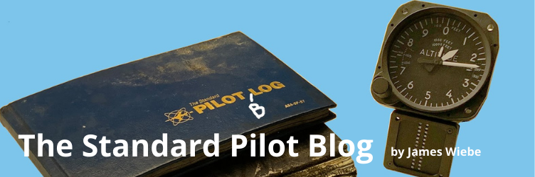
Place 4 spacer blocks on your table, so that each spar will have support off the table at each end. We like to use leftover large plastic wire spools, but you can make them out of wooden blocks or whatever you want. Exact uniform height is critical. (A flat work surface is critical as well.) The height should allow enough room for you to apply glue from the underside of the wing assembly.
 |
| Spar sitting on spacer block (wire spool, in this case) |
The spacer block on the leading edge of the wingtip end must have an additional block of 1/2 inch thickness. This puts a slight amount of twist into the wing. This twist will ensure that the tips of the wing stalls before the inboard section. You can see that a block of appropriate thickness has been inserted in the picture, below:
 |
| 0.5" spacer in between wire spool and spar at OUTBOARD FRONT SPAR |
7. Aluminum Rib placement and gluing
Make sure you keep everything absolutely square as ribs are placed and glued. This is critical to building a quality wing which will fly true.
After placing the carbon fiber spars on the blocks, each aluminum rib can be slipped onto the spars to their correct position. Use squares and clamps to make sure that each rib is perfectly square to work surface and to the spars. The leading edge spar will be attached to each aluminum rib using an aluminum strap.
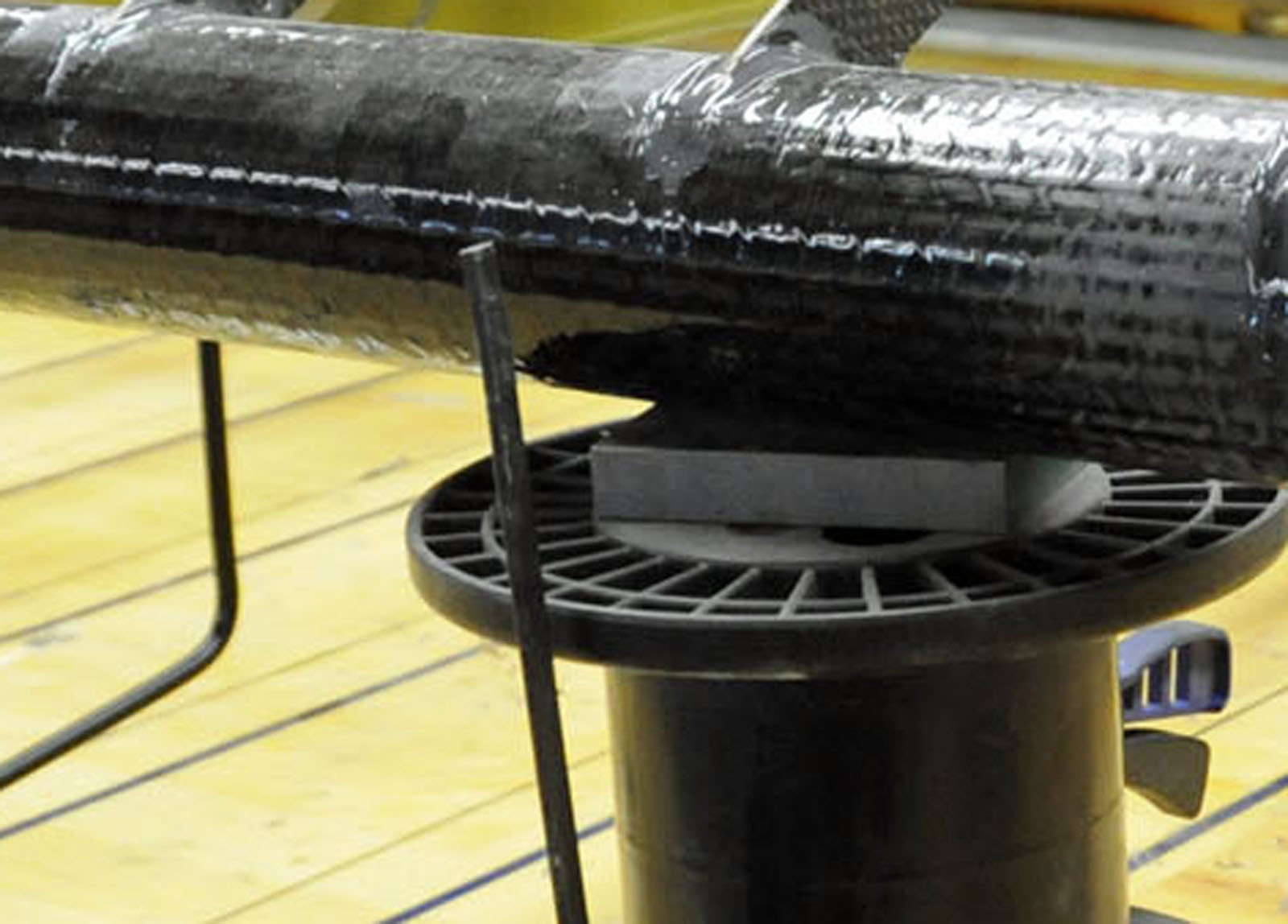
Glue the rear spar to each aluminum rib using a uniform filet of 3M 2216 glue.
 |
| Glue Filet around around spar / rib joint |
Rivet the front straps to the bottom of each rib using two rivets. Apply 2216 glue to the front of each spar. Rivet the front straps to the top of each rib. It may be helpful to predrill these holes and clamp the straps in place using clecos.
 |
| Rib strip and glue around front spar. |
8. Attach the wooden wingtip rib.
The wingtip rib is CNC machined to accommodate 2.5 inch diameter spar tubes; the supplied carbon fiber tubes are approximately 2.4 inches in diameter. Utilize small spacers (for instance, wooden toothpicks) to ensure that the wingtip rib is properly and uniformly positioned around the spar. Bond the wooden wingtip rib to the spars using a liberal amount of 2216 adhesive. (This particular wing has aluminum spar extensions shown in the photo, below).
 |
| Wingtip wooden ribs glued to front and rear spar. Spar extensions are shown in this photo as well. |
9. Attach the wing root spar doubler to the carbon fiber spars.
The wing root spar doubler have to be installed after the ribs have been slipped over the spars. Remember that you prepared for this process in step #2. After applying 3M 2216 glue, slip each of the 6 inch wing root spar doublers over the carbon fiber spars.
10. Attach the wooden root rib and tripler.
Using 2216, attach the wooden root rib. Then attach the 1.5 inch tripler tubing using more 2216.
 |
| Root wooden rib. |
 |
| Leading edge of root wooden rib. Doubler (zinc phosphated) and tripler (bare aluminum for clarity) are also shown. Excess 2216 must be removed before it sets. It may also be removed by using a rasp after it sets. |
The following 3 photos show the front spar double / tripler and wooden root rib after the 2216 epoxy has set, and been cleaned up. We have also ground the spar end and doubler/tripler down to an exact distance of 1.5 inches from the root rib. Note the clean lines. Still remaining is the rivet placement, and the removal of excess material on the rear spar. (Required for wing folding.)


It's now time to place the reinforcing rivets. The front spar receives 12 rivets. Look at the following picture for placement.

The rear spar doubler/tripler receives just 8 rivets: 6 on the front; 2 on the rear. This will accommodate the large notch which needs to be made to the rear attachment point, so that it will fold backward.
 |
| A large portion of this doubler/tripler will be cut off, to allow the wing to fold backwards. 6 rivets on other side of rear spar are not visible in this photo. The open area (between the 2 rivets in the picture) will be relieved after wing mounting, in order to allow wing to fold backwards. |
11. Attach the rib stiffeners.
The two ribs on either side of the lift struts have a square aluminum stiffener riveted and glued to them. Glue the stiffeners on with 3M 2216 and also use rivets.
 |
| Each of the two ribs in this photo has a square tube (rib stiffener) attached to it. Note Zinc Phosphate on all aluminum. |
12. Attach the false ribs.
Slip the 1/2 inch aluminum tubing (false rib spar) all of the way through the entire wing, threading 3 false ribs per wing section. If the 1/2 inch wooden root and tip holes don't exactly line up with the holes in the aluminum ribs, recut the wooden rib holes as necessary. If the 1/2 inch aluminum tube is not long enough, join two sections together using a short (6 inch) ferrule spacer and 3M 2216 glue. After slipping through the ribs, ensure the joint is lined up with one of the ribs. Line up all false ribs and epoxy to the 1/2 inch aluminum false rib spar and to the leading edge spar using our favorite glue, 3M 2216.
 |
| False ribs glued to false rib spar and leading edge spar. |
 |
| False Rib Spar, looking down the top of the wing. |
13. Attach the trailing edge.
Like all other aluminum, you need to spray coat the trailing edge with Zinc Phosphate.
Notch the trailing edge material as required to slip over each rib.
 |
| Notch both the top and the bottom of the trailing edge material. This will be glued and riveted later. |
You'll want to wait to rivet the trailing edge; the installation of the flaperon hard points and trim plates should be done before the trailing edge is riveted down.
14. Attach the flaperon drop strut.
Each wing has a unique (Left or Right) dropper. The flaperon dropper is CNC machined from 6061T6 aluminum and is mounted to the first aluminum rib.
 |
| Left Wing Flaperon Dropper. CNC Machined from 6061T6. |
The bottom of the flaperon dropper is designed to directly accept a flaperon push pull cable.
 |
| Bottom of flaperon dropper. |
After fully pressing a cable into the slot, it is locked into place by slipping a cotter key through the small hole. The picture below shows the way this is started:

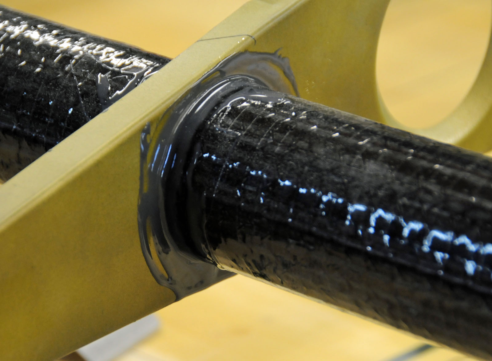
This piece is attached to the wing using 2216 adhesive and AN3 hardware. Here is its placement on the wing:
 |
| Left wing flaperon dropper, showing placement to rib. |
In the left wing, it is installed flush to the rib. In the right wing, it is installed flush to the inside of the rib. This uneven spacing allows the wings to fold backwards without the flaperon control cables from hitting each other.
 |
| Left wing with flaperon dropper glued with 3M 2216 and bolted with AN3 hardware. |
 |
| Right wing flaperon dropper. Compare to left wing to understand placement. Note notch in rib and placement inside rib. |
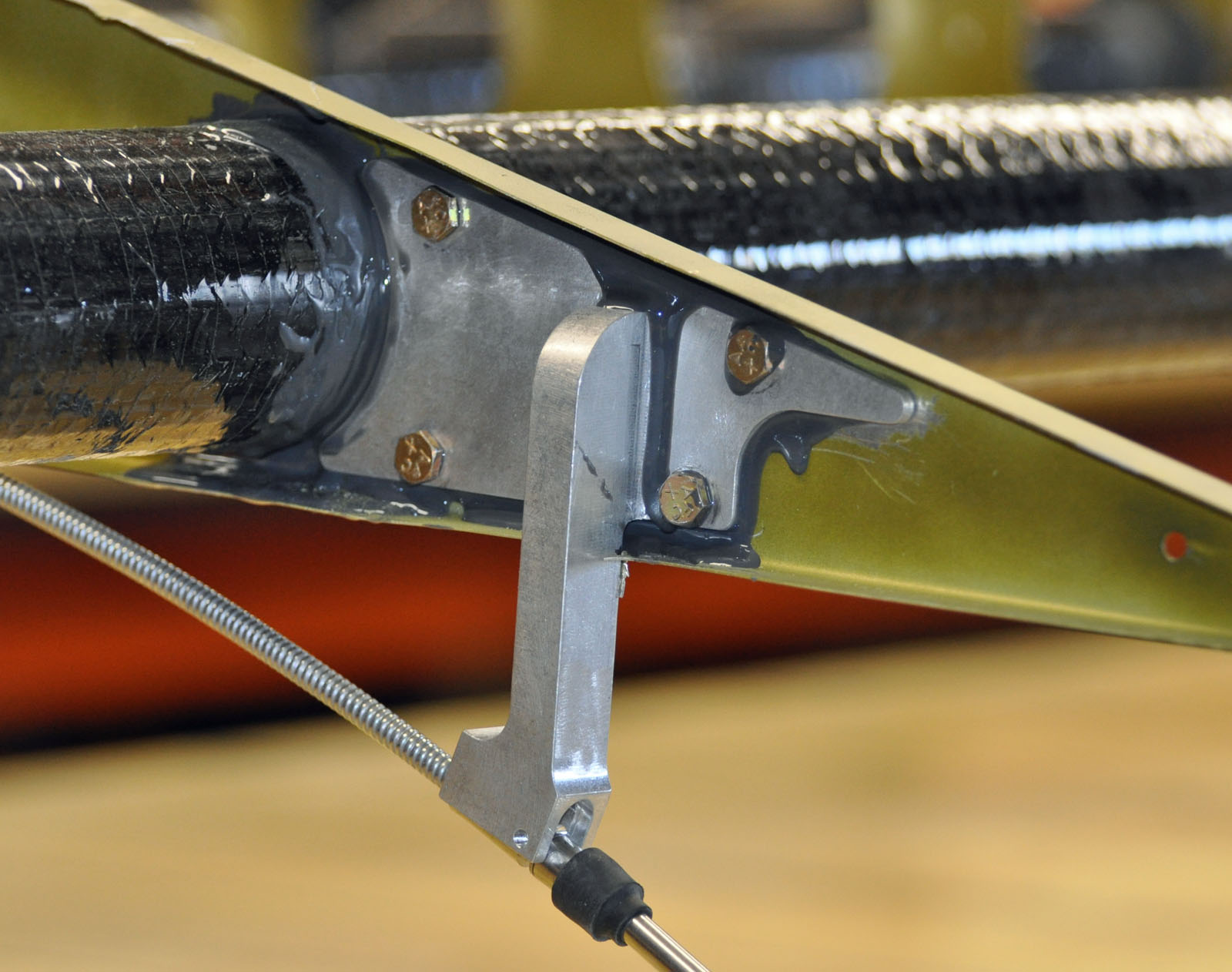
15. Attach the jury strut fittings.
Each of the jury strut fittings is attached to the carbon fiber struts using 3M 2216 glue and carbon fiber rope with epoxy. Here's a picture of the jury strut fitting, prior to attachment:
 |
| Jury strut attachment, machined from 6061T6 aluminum. |
 |
| Jury Strut fitting, glued to bottom of spar with 3M 2216. |
After attaching the strut fitting to the spar using 3M 2216, we then tightly wrap the jury strut and spar with carbon fiber rope. We then carefully paint the rope / jury strut assembly with a modest amount of conventional (West systems or equivalent) epoxy. Here is what it looks like:
 |
| Jury Strut fitting attached with Carbon Fiber rope and epoxy |
6 comments:
I seem to recall that in aircraft with ailerons, the tips of the wings are warped down in front so the tips and aileron control surfaces would be the last to stall. With flaperons, control should still be possible near the root when the wing tips are warped up to stall first, but why is that more desireable?
I am also wondering why your washout is L.E. positive and not negative?
+1 on wondering why you are adding wash-in rather than wash-out to the wing. What is the advantage of causing tip stall to precede root stall? Slick looking wing by the way!
Hi everyone, the wings are now built neutral and any twist may be put in via strut adjustment. FWIW, this doesn't seem to have much (any?) effect on stall characteristics -- James
Great post. I came across your post while looking up push pull cable systems. This is very interesting, my fiance would love it. I will have to send it to him. Thanks so much for sharing!
Hi,
What is the wing dimensions?
Post a Comment